
بسم الله الرحمن الرحيم Projection Theory








Description: بسم الله الرحمن الرحيم Projection Theory Projection is a method to represent 3D object into 2D plane(paperetc.) Object View Therefore we need at least tow or three views (except for especial cases) Projection Parameters The projection
Related Topics
Download Presentation
"بسم الله الرحمن الرحيم Projection Theory" is the property of its rightful owner. Permission is granted to download and print the materials on this website for personal, non-commercial use only, and to display it on your personal computer provided you do not modify the materials and that you retain all copyright notices contained in the materials. By downloading content from our website, you accept the terms of this agreement.
Presentation Transcript
slide1. بسم الله الرحمن الرحيم<br>
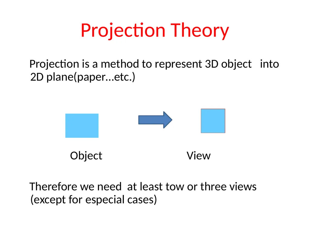
slide2. Projection Theory Projection is a method to represent 3D object into 2D plane(paper…etc.)
Object View
Therefore we need at least tow or three views (except for especial cases)<br>
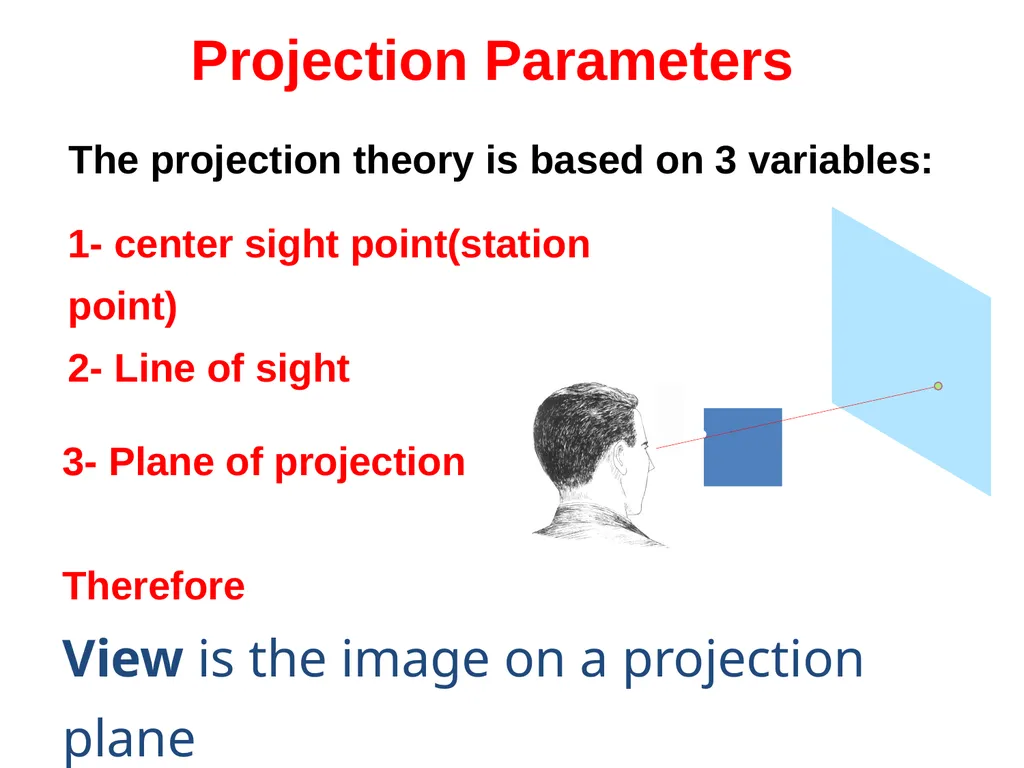
slide3. Projection Parameters The projection theory is based on 3 variables: 3- Plane of projection
Therefore
View is the image on a projection plane 1- center sight point(station point)
2- Line of sight<br>
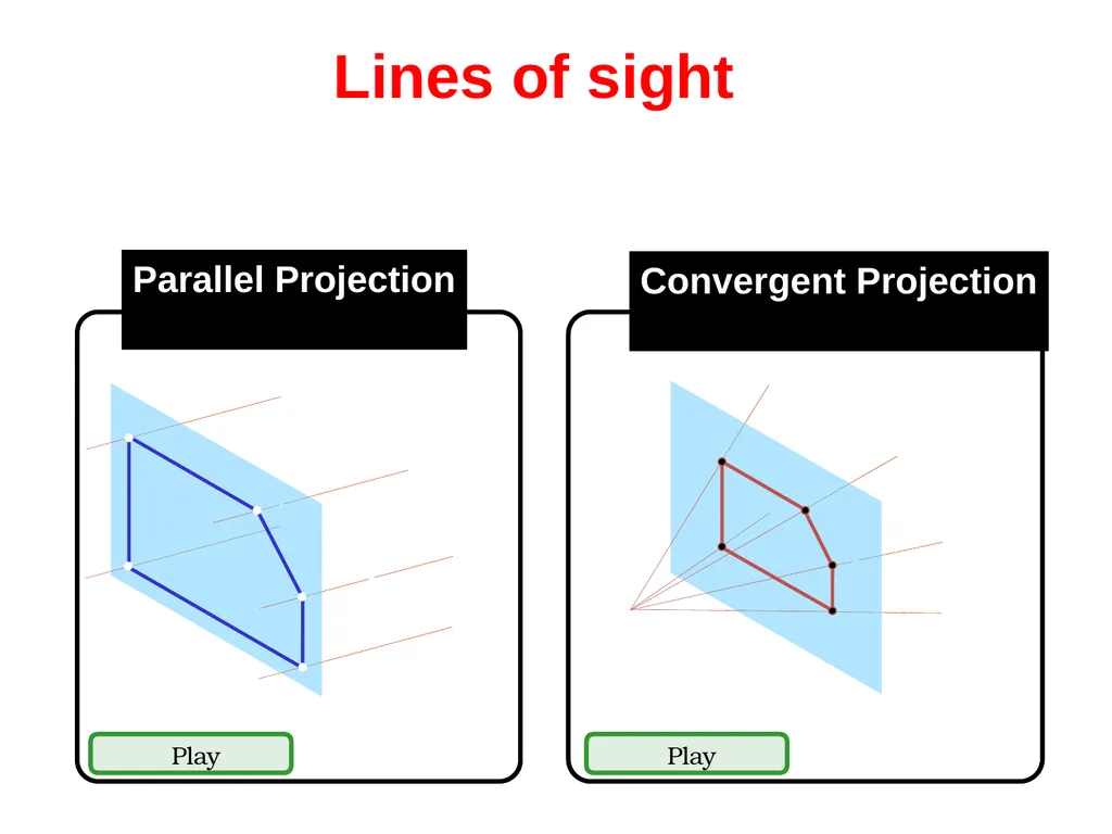
slide4. Lines of sight Lines of Convergent Projection Parallel Projection<br>
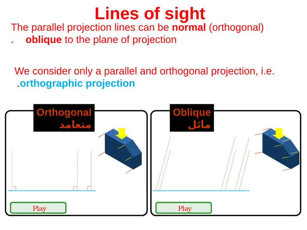
slide5. The parallel projection lines can be normal (orthogonal) or oblique to the plane of projection. Oblique
مائل Orthogonal
متعامد We consider only a parallel and orthogonal projection, i.e. orthographic projection. Lines of sight<br>
slide6. Rotation
دوران Tilting
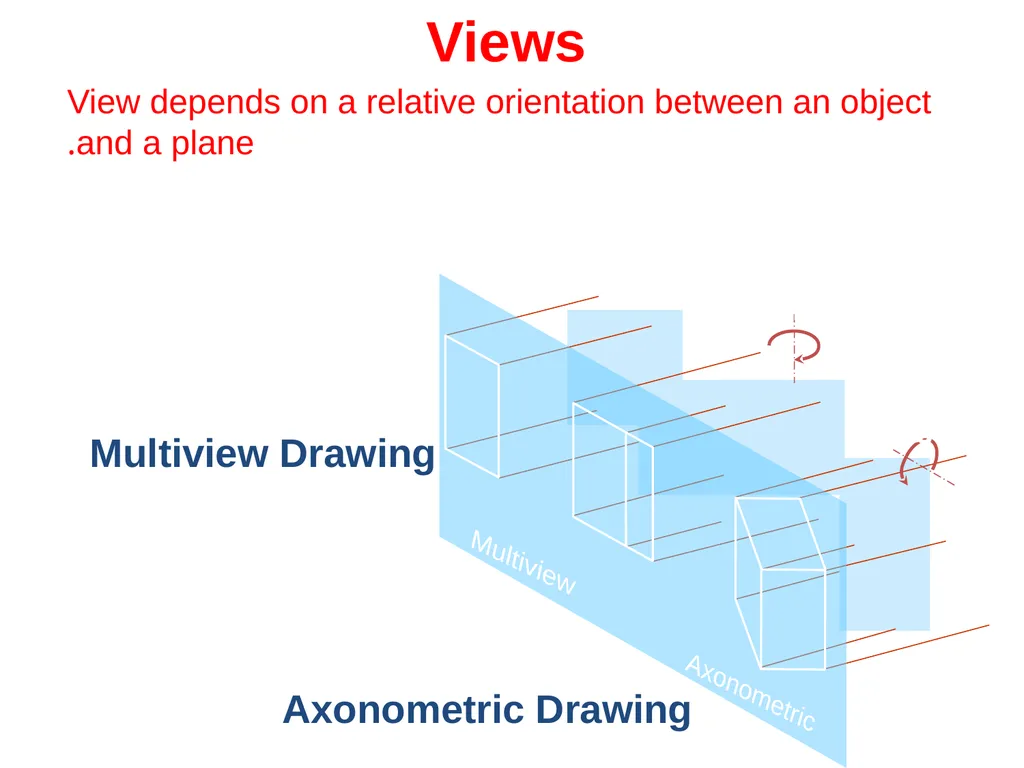
امالة Axonometric Multiview Multiview Drawing Views View depends on a relative orientation between an object and a plane. Normal
عمودى Axonometric Drawing<br>
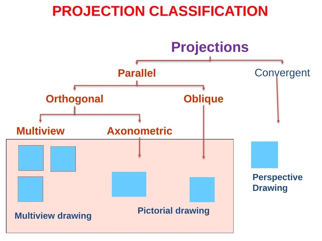
slide7. PROJECTION CLASSIFICATION Projections Convergent Parallel Orthogonal Oblique Axonometric Multiview Pictorial drawing Perspective
Drawing Multiview drawing<br>
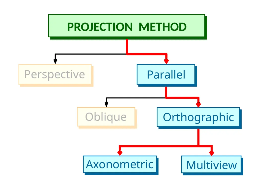
slide8. PROJECTION METHOD<br>
slide9. MULTIVIEW DRAWING<br>
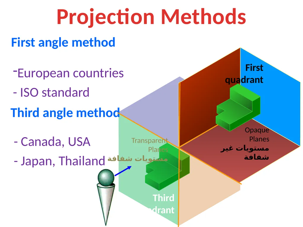
slide10. Projection Methods First angle method Third angle method First
quadrant Third
quadrant European countries
- ISO standard - Canada, USA - Japan, Thailand Transparent
Planes
مستويات شفافة Opaque
Planes
مستويات غير شفافة<br>
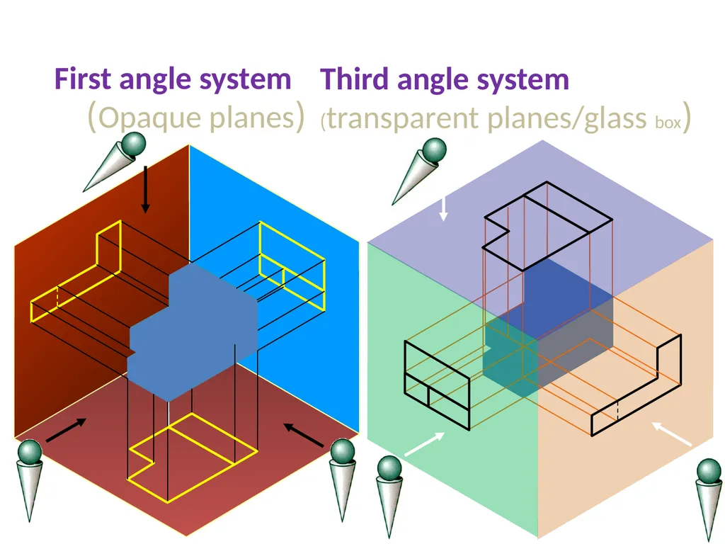
slide11. First angle system
(Opaque planes) Third angle system
(transparent planes/glass box)<br>
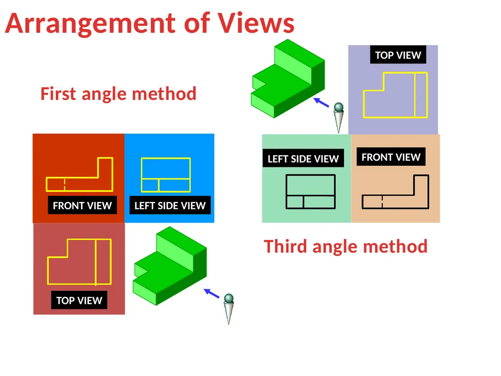
slide12. FRONT VIEW LEFT SIDE VIEW TOP VIEW Arrangement of Views First angle method Third angle method LEFT SIDE VIEW FRONT VIEW TOP VIEW<br>
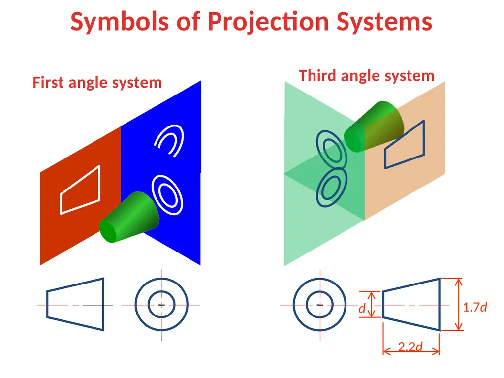
slide13. Symbols of Projection Systems First angle system Third angle system<br>
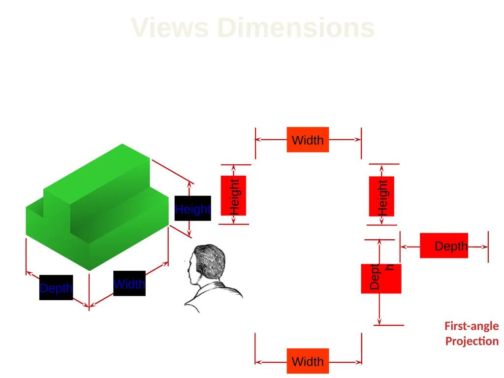
slide14. Views Dimensions First-angle
Projection<br>
slide15. Projections of points, lines and planes<br>
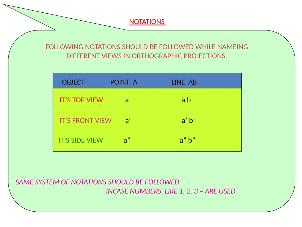
slide16. NOTATIONS FOLLOWING NOTATIONS SHOULD BE FOLLOWED WHILE NAMEING
DIFFERENT VIEWS IN ORTHOGRAPHIC PROJECTIONS. IT’S FRONT VIEW a’ a’ b’ SAME SYSTEM OF NOTATIONS SHOULD BE FOLLOWED
INCASE NUMBERS, LIKE 1, 2, 3 – ARE USED. OBJECT POINT A LINE AB IT’S TOP VIEW a a b IT’S SIDE VIEW a” a” b”<br>
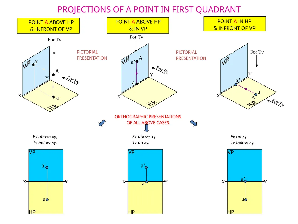
slide17. A a a’ A a a’ A a a’ X Y PROJECTIONS OF A POINT IN FIRST QUADRANT PICTORIAL
PRESENTATION PICTORIAL
PRESENTATION Fv above xy,
Tv below xy. Fv above xy,
Tv on xy. Fv on xy,
Tv below xy.<br>
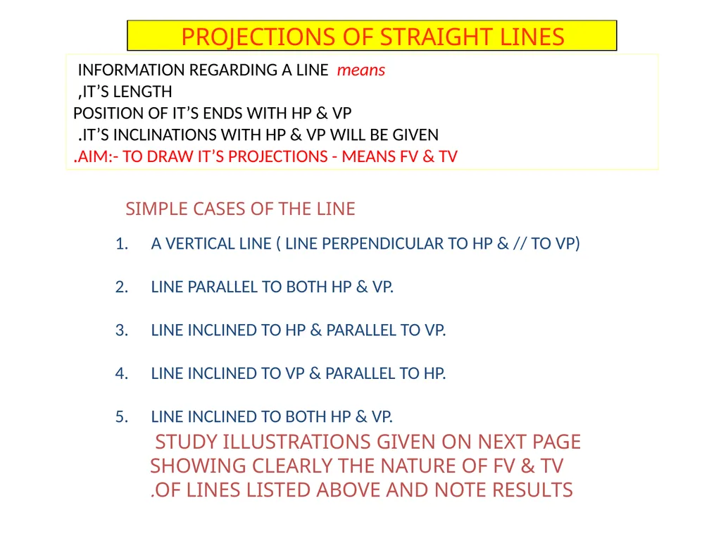
slide18. SIMPLE CASES OF THE LINE A VERTICAL LINE ( LINE PERPENDICULAR TO HP & // TO VP)
LINE PARALLEL TO BOTH HP & VP.
LINE INCLINED TO HP & PARALLEL TO VP.
LINE INCLINED TO VP & PARALLEL TO HP.
LINE INCLINED TO BOTH HP & VP. STUDY ILLUSTRATIONS GIVEN ON NEXT PAGE
SHOWING CLEARLY THE NATURE OF FV & TV
OF LINES LISTED ABOVE AND NOTE RESULTS. INFORMATION REGARDING A LINE means
IT’S LENGTH,
POSITION OF IT’S ENDS WITH HP & VP
IT’S INCLINATIONS WITH HP & VP WILL BE GIVEN.
AIM:- TO DRAW IT’S PROJECTIONS - MEANS FV & TV.<br>
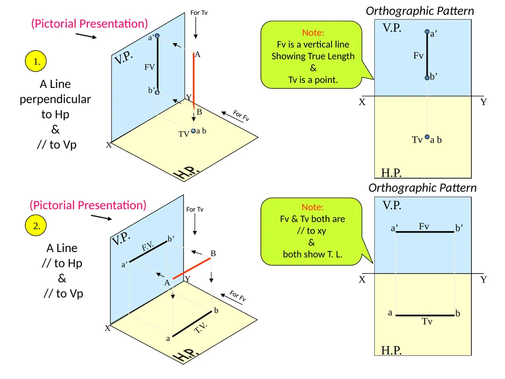
slide19. F.V. T.V. a b TV FV For Fv For Tv For Tv For Fv 1. 2. A Line
perpendicular
to Hp
&
// to Vp A Line
// to Hp
&
// to Vp Orthographic Pattern Orthographic Pattern<br>
slide20. A Line inclined to Hp
and
parallel to Vp
(Pictorial presentation) A Line inclined to Vp
and
parallel to Hp
(Pictorial presentation) Ø F.V. T.V. 3. 4. Orthographic Projections<br>
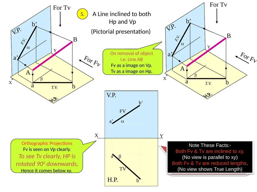
slide21. A Line inclined to both
Hp and Vp
(Pictorial presentation) 5.<br>
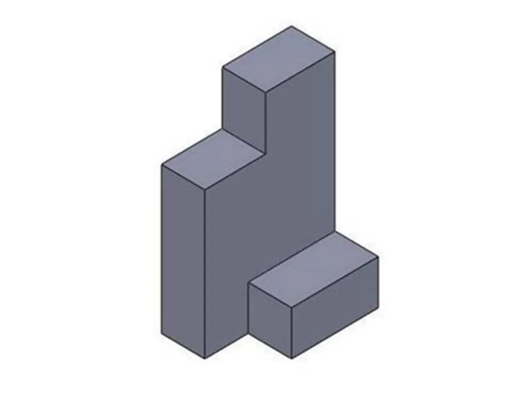
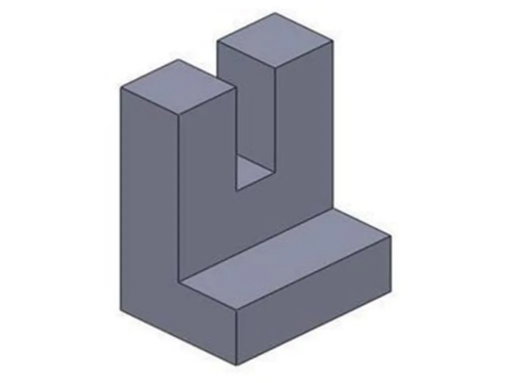
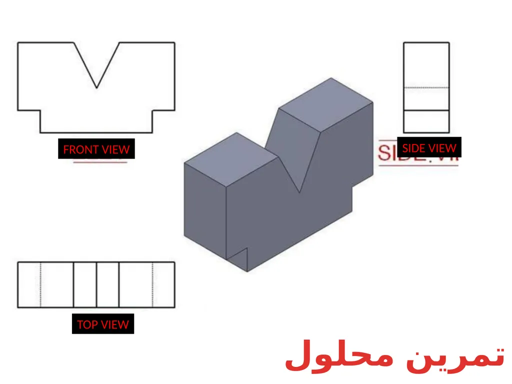
slide26. تمرين محلول TOP VIEW FRONT VIEW SIDE VIEW<br>
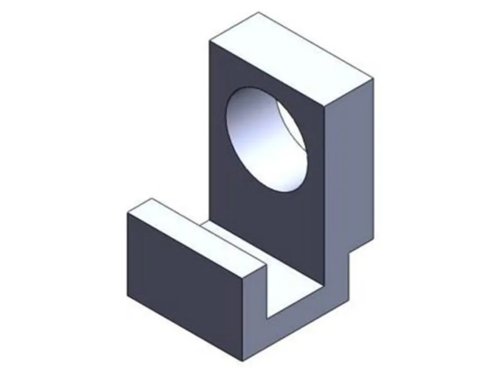
slide27. تمرين محلول TOP VIEW FRONT VIEW SIDE VIEW<br>
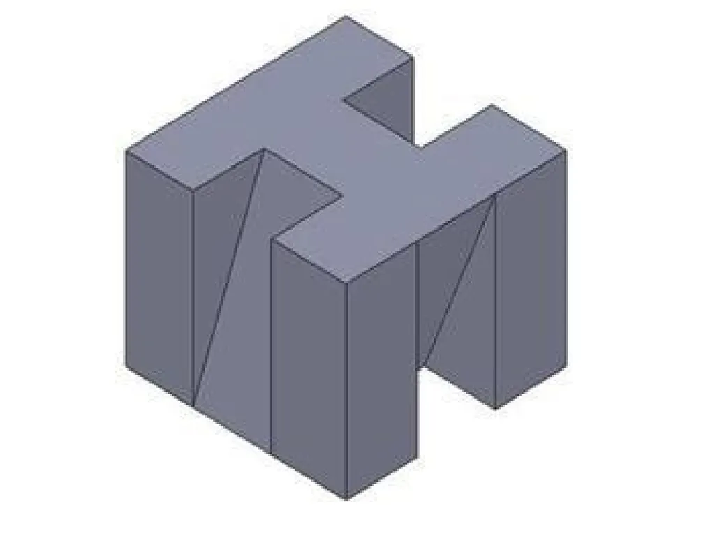
slide28. تمرين محلول TOP VIEW FRONT VIEW SIDE VIEW<br>
slide29. تمرين محلول TOP VIEW FRONT VIEW SIDE VIEW<br>
slide30. تمرين محلول TOP VIEW FRONT VIEW SIDE VIEW<br>
slide31. تمرين محلول TOP VIEW FRONT VIEW SIDE VIEW<br>
slide32. تمرين محلول TOP VIEW FRONT VIEW SIDE VIEW<br>
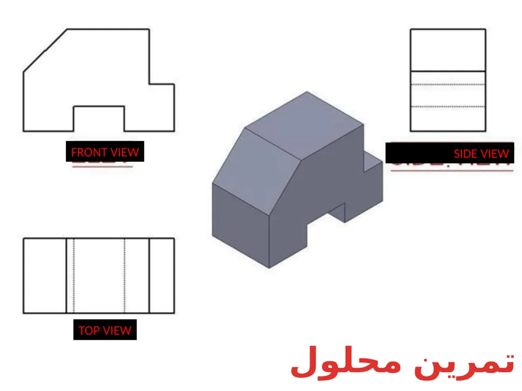
slide33. FRONT VIEW SIDE VIEW TOP VIEW تمرين محلول<br>
slide34. FRONT VIEW TOP VIEW SIDE VIEW تمرين محلول<br>
slide35. تمرين محلول SIDE VIEW FRONT VIEW TOP VIEW<br>
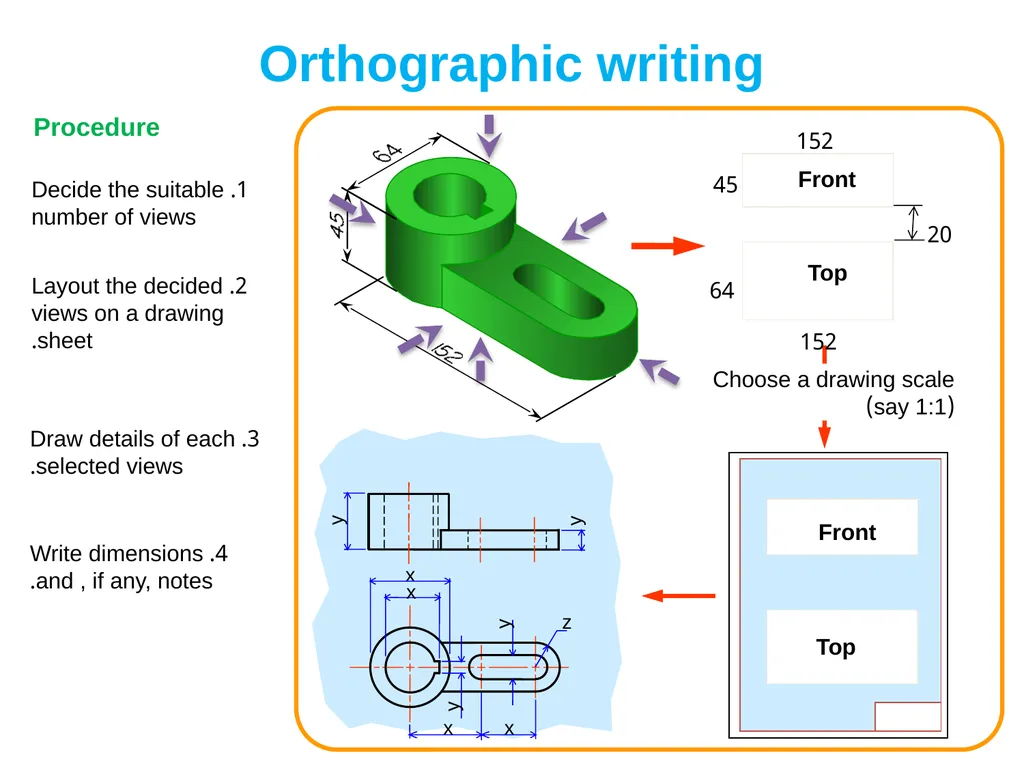
slide36. Procedure 1. Decide the suitable number of views 2. Layout the decided views on a drawing sheet. 3. Draw details of each selected views. 4. Write dimensions and , if any, notes. 64 152 152 45 20 Top Front Choose a drawing scale
(say 1:1) Top Front Orthographic writing<br>
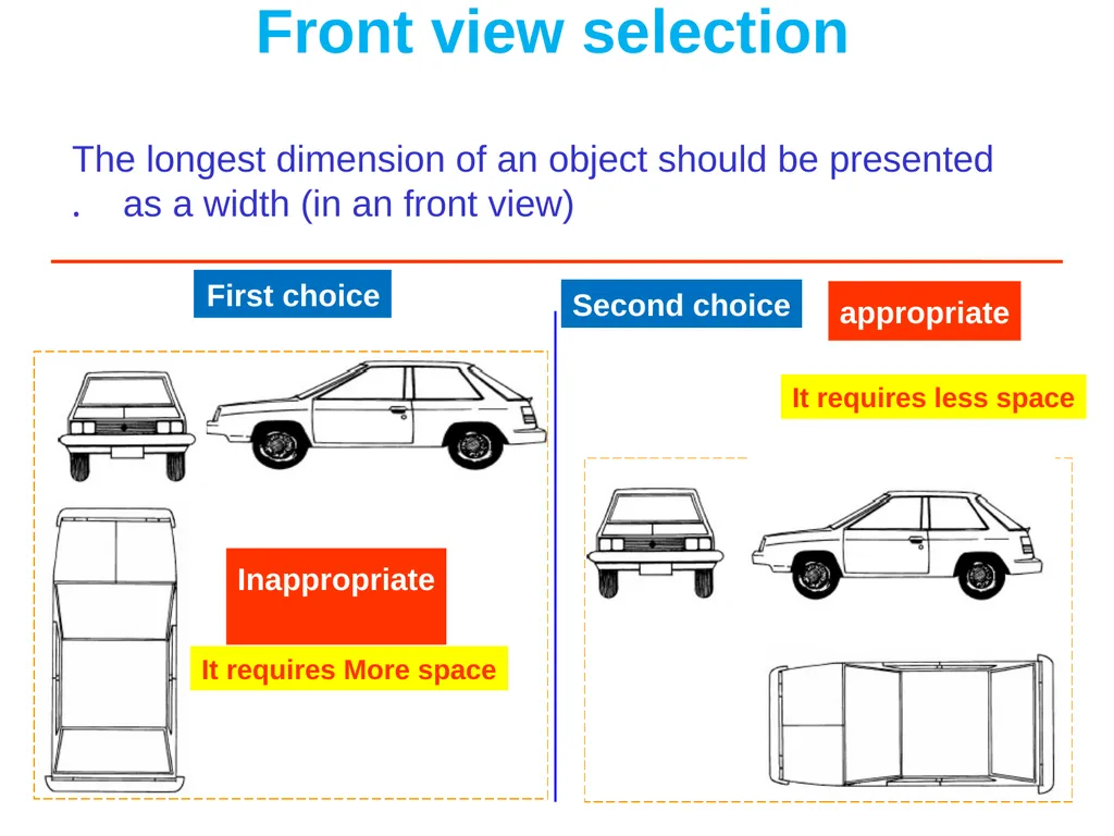
slide37. Front view selection The longest dimension of an object should be presented as a width (in an front view). Inappropriate First choice Second choice appropriate It requires More space It requires less space<br>
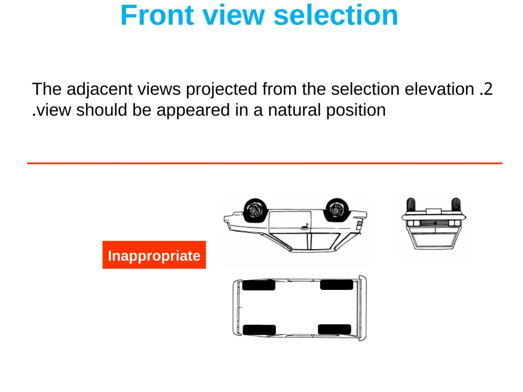
slide38. Inappropriate 2. The adjacent views projected from the selection elevation view should be appeared in a natural position. Front view selection<br>
slide39. 3. It has the fewest number of hidden lines. Good Inappropriate Front view selection<br>
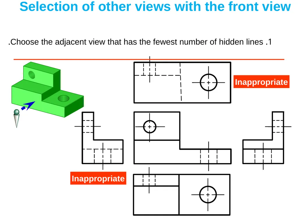
slide40. Inappropriate Inappropriate 1. Choose the adjacent view that has the fewest number of hidden lines. Selection of other views with the front view<br>
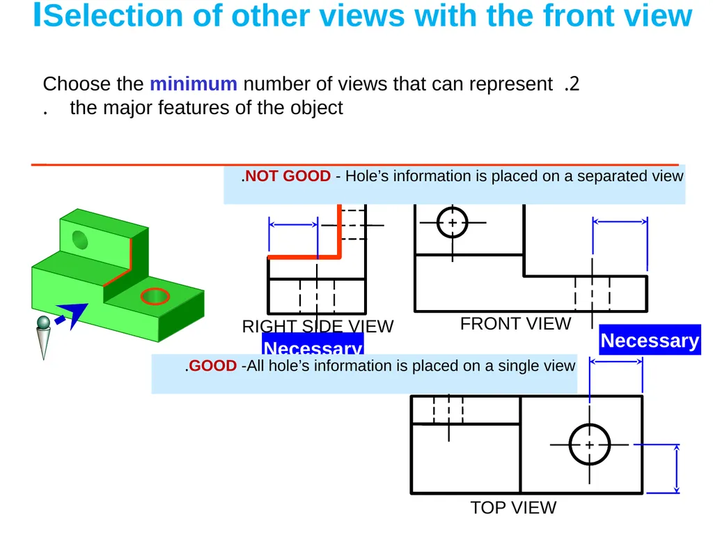
slide41. 2. Choose the minimum number of views that can represent the major features of the object. Necessary Necessary NOT GOOD - Hole’s information is placed on a separated view. GOOD -All hole’s information is placed on a single view. Selection of other views with the front viewا FRONT VIEW TOP VIEW RIGHT SIDE VIEW<br>
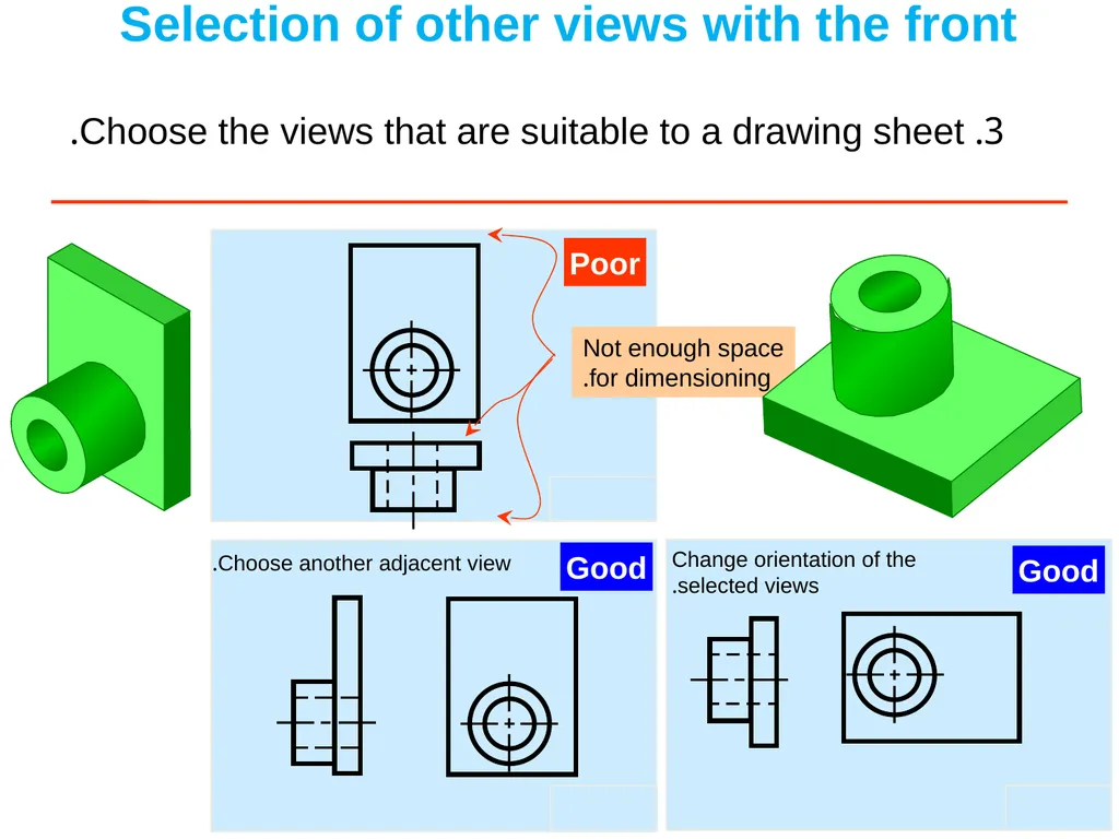
slide42. 3. Choose the views that are suitable to a drawing sheet. Good Poor Not enough space
for dimensioning. Good Choose another adjacent view. Change orientation of the
selected views. Selection of other views with the front<br>
slide43. Examples
on
view selection<br>
slide44. Important Notes Generally, three views of orthographic drawing are enough to describes an object’s information. 2. In some specific cases, a necessary view may be less or more than three views.<br>
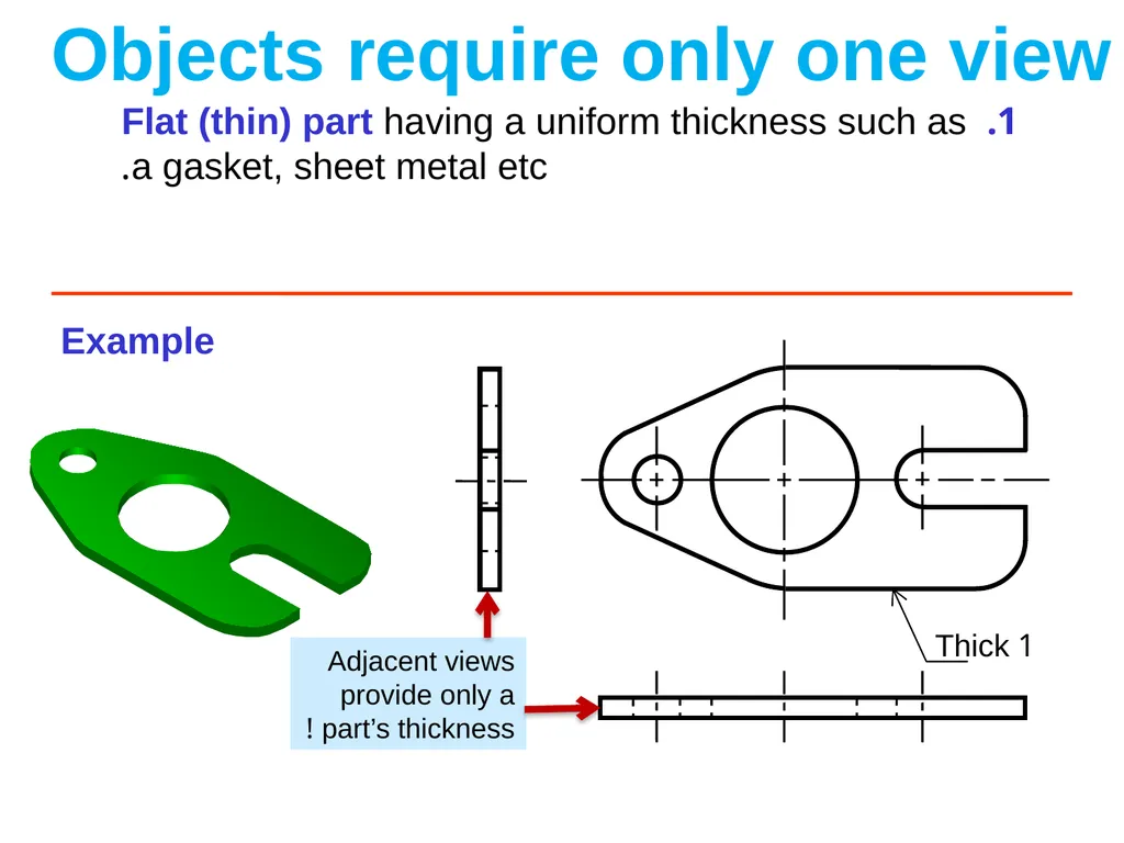
slide45. Objects require only one view 1. Flat (thin) part having a uniform thickness such as a gasket, sheet metal etc. Adjacent views provide only a
part’s thickness ! 1 Thick Example<br>
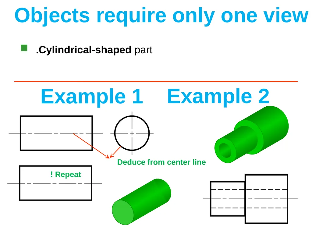
slide46. Repeat ! Deduce from center line Example 1 Example 2 Cylindrical-shaped part. Objects require only one view<br>
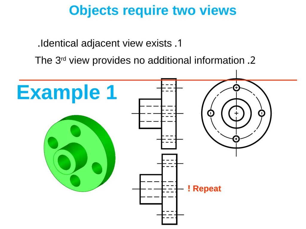
slide47. 1. Identical adjacent view exists. Repeat ! 2. The 3rd view provides no additional information Example 1 Objects require two views<br>
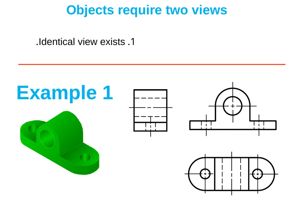
slide48. 1. Identical view exists. Example 1 Objects require two views<br>
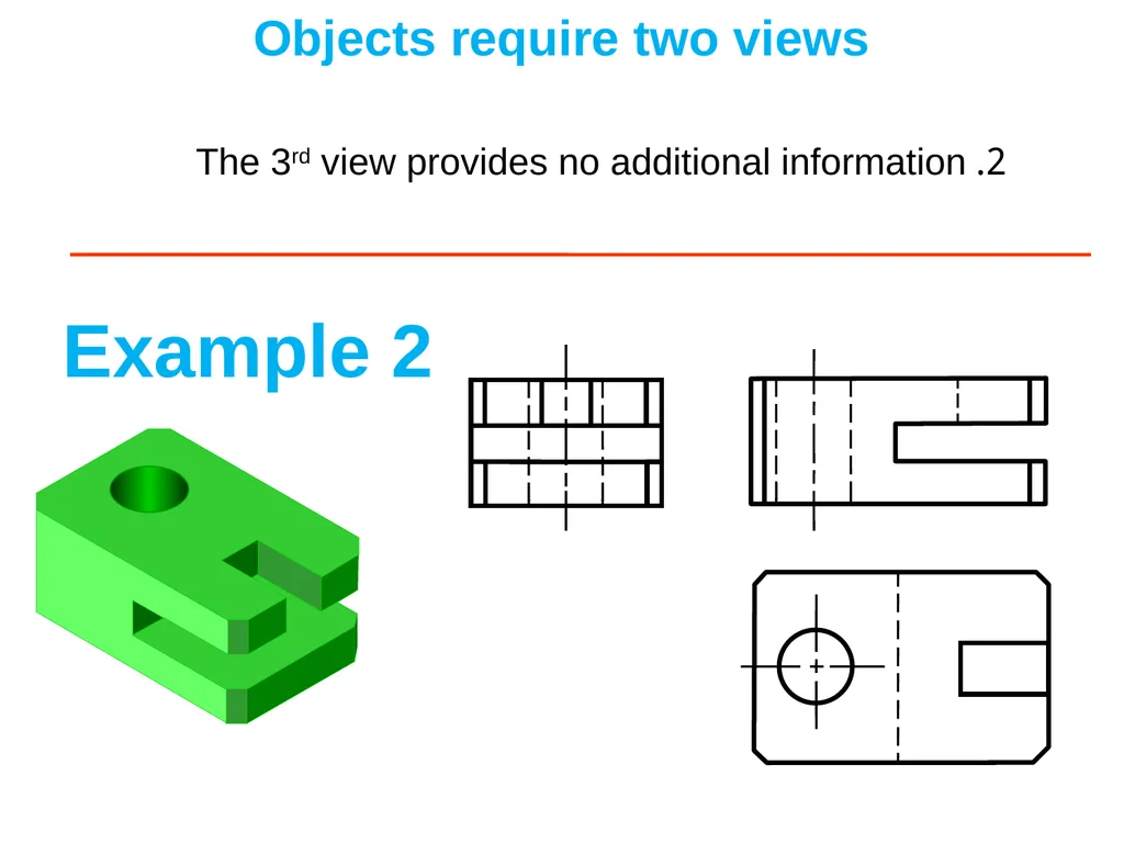
slide49. Example 2 2. The 3rd view provides no additional information Objects require two views<br>
slide50. EXAMPLES FOR ORTHOGRAPHIC
PROJECTIONS<br>
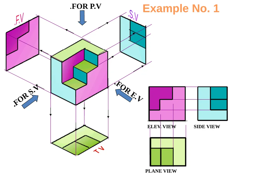
slide51. ELEV. VIEW PLANE VIEW SIDE VIEW FOR E.V. FOR S.V. FOR P.V. F.V. S.V. Example No. 1<br>
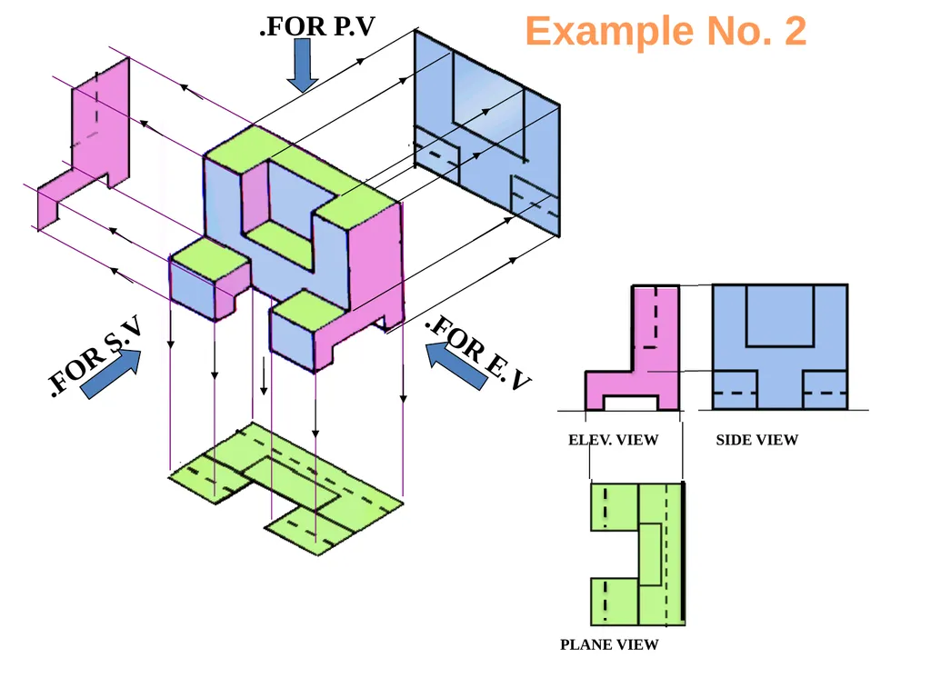
slide52. FOR E.V. FOR S.V. FOR P.V. ELEV. VIEW PLANE VIEW SIDE VIEW Example No. 2<br>
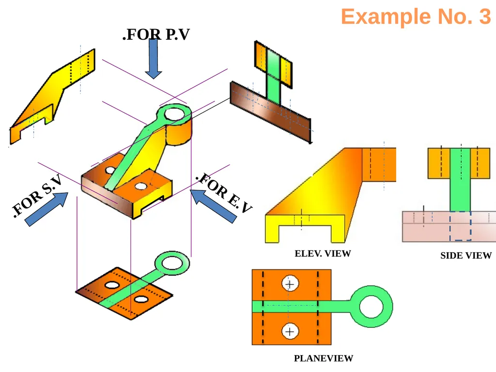
slide53. ELEV. VIEW PLANEVIEW SIDE VIEW Example No. 3<br>
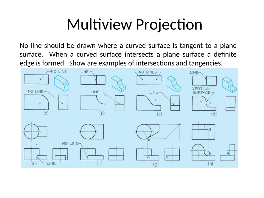
slide54. Multiview Projection No line should be drawn where a curved surface is tangent to a plane surface. When a curved surface intersects a plane surface a definite edge is formed. Show are examples of intersections and tangencies.<br>
slide55. END<br>
slide2. Projection Theory Projection is a method to represent 3D object into 2D plane(paper…etc.)
Object View
Therefore we need at least tow or three views (except for especial cases)<br>
slide3. Projection Parameters The projection theory is based on 3 variables: 3- Plane of projection
Therefore
View is the image on a projection plane 1- center sight point(station point)
2- Line of sight<br>
slide4. Lines of sight Lines of Convergent Projection Parallel Projection<br>
slide5. The parallel projection lines can be normal (orthogonal) or oblique to the plane of projection. Oblique
مائل Orthogonal
متعامد We consider only a parallel and orthogonal projection, i.e. orthographic projection. Lines of sight<br>
slide6. Rotation
دوران Tilting
امالة Axonometric Multiview Multiview Drawing Views View depends on a relative orientation between an object and a plane. Normal
عمودى Axonometric Drawing<br>
slide7. PROJECTION CLASSIFICATION Projections Convergent Parallel Orthogonal Oblique Axonometric Multiview Pictorial drawing Perspective
Drawing Multiview drawing<br>
slide8. PROJECTION METHOD<br>
slide9. MULTIVIEW DRAWING<br>
slide10. Projection Methods First angle method Third angle method First
quadrant Third
quadrant European countries
- ISO standard - Canada, USA - Japan, Thailand Transparent
Planes
مستويات شفافة Opaque
Planes
مستويات غير شفافة<br>
slide11. First angle system
(Opaque planes) Third angle system
(transparent planes/glass box)<br>
slide12. FRONT VIEW LEFT SIDE VIEW TOP VIEW Arrangement of Views First angle method Third angle method LEFT SIDE VIEW FRONT VIEW TOP VIEW<br>
slide13. Symbols of Projection Systems First angle system Third angle system<br>
slide14. Views Dimensions First-angle
Projection<br>
slide15. Projections of points, lines and planes<br>
slide16. NOTATIONS FOLLOWING NOTATIONS SHOULD BE FOLLOWED WHILE NAMEING
DIFFERENT VIEWS IN ORTHOGRAPHIC PROJECTIONS. IT’S FRONT VIEW a’ a’ b’ SAME SYSTEM OF NOTATIONS SHOULD BE FOLLOWED
INCASE NUMBERS, LIKE 1, 2, 3 – ARE USED. OBJECT POINT A LINE AB IT’S TOP VIEW a a b IT’S SIDE VIEW a” a” b”<br>
slide17. A a a’ A a a’ A a a’ X Y PROJECTIONS OF A POINT IN FIRST QUADRANT PICTORIAL
PRESENTATION PICTORIAL
PRESENTATION Fv above xy,
Tv below xy. Fv above xy,
Tv on xy. Fv on xy,
Tv below xy.<br>
slide18. SIMPLE CASES OF THE LINE A VERTICAL LINE ( LINE PERPENDICULAR TO HP & // TO VP)
LINE PARALLEL TO BOTH HP & VP.
LINE INCLINED TO HP & PARALLEL TO VP.
LINE INCLINED TO VP & PARALLEL TO HP.
LINE INCLINED TO BOTH HP & VP. STUDY ILLUSTRATIONS GIVEN ON NEXT PAGE
SHOWING CLEARLY THE NATURE OF FV & TV
OF LINES LISTED ABOVE AND NOTE RESULTS. INFORMATION REGARDING A LINE means
IT’S LENGTH,
POSITION OF IT’S ENDS WITH HP & VP
IT’S INCLINATIONS WITH HP & VP WILL BE GIVEN.
AIM:- TO DRAW IT’S PROJECTIONS - MEANS FV & TV.<br>
slide19. F.V. T.V. a b TV FV For Fv For Tv For Tv For Fv 1. 2. A Line
perpendicular
to Hp
&
// to Vp A Line
// to Hp
&
// to Vp Orthographic Pattern Orthographic Pattern<br>
slide20. A Line inclined to Hp
and
parallel to Vp
(Pictorial presentation) A Line inclined to Vp
and
parallel to Hp
(Pictorial presentation) Ø F.V. T.V. 3. 4. Orthographic Projections<br>
slide21. A Line inclined to both
Hp and Vp
(Pictorial presentation) 5.<br>
slide26. تمرين محلول TOP VIEW FRONT VIEW SIDE VIEW<br>
slide27. تمرين محلول TOP VIEW FRONT VIEW SIDE VIEW<br>
slide28. تمرين محلول TOP VIEW FRONT VIEW SIDE VIEW<br>
slide29. تمرين محلول TOP VIEW FRONT VIEW SIDE VIEW<br>
slide30. تمرين محلول TOP VIEW FRONT VIEW SIDE VIEW<br>
slide31. تمرين محلول TOP VIEW FRONT VIEW SIDE VIEW<br>
slide32. تمرين محلول TOP VIEW FRONT VIEW SIDE VIEW<br>
slide33. FRONT VIEW SIDE VIEW TOP VIEW تمرين محلول<br>
slide34. FRONT VIEW TOP VIEW SIDE VIEW تمرين محلول<br>
slide35. تمرين محلول SIDE VIEW FRONT VIEW TOP VIEW<br>
slide36. Procedure 1. Decide the suitable number of views 2. Layout the decided views on a drawing sheet. 3. Draw details of each selected views. 4. Write dimensions and , if any, notes. 64 152 152 45 20 Top Front Choose a drawing scale
(say 1:1) Top Front Orthographic writing<br>
slide37. Front view selection The longest dimension of an object should be presented as a width (in an front view). Inappropriate First choice Second choice appropriate It requires More space It requires less space<br>
slide38. Inappropriate 2. The adjacent views projected from the selection elevation view should be appeared in a natural position. Front view selection<br>
slide39. 3. It has the fewest number of hidden lines. Good Inappropriate Front view selection<br>
slide40. Inappropriate Inappropriate 1. Choose the adjacent view that has the fewest number of hidden lines. Selection of other views with the front view<br>
slide41. 2. Choose the minimum number of views that can represent the major features of the object. Necessary Necessary NOT GOOD - Hole’s information is placed on a separated view. GOOD -All hole’s information is placed on a single view. Selection of other views with the front viewا FRONT VIEW TOP VIEW RIGHT SIDE VIEW<br>
slide42. 3. Choose the views that are suitable to a drawing sheet. Good Poor Not enough space
for dimensioning. Good Choose another adjacent view. Change orientation of the
selected views. Selection of other views with the front<br>
slide43. Examples
on
view selection<br>
slide44. Important Notes Generally, three views of orthographic drawing are enough to describes an object’s information. 2. In some specific cases, a necessary view may be less or more than three views.<br>
slide45. Objects require only one view 1. Flat (thin) part having a uniform thickness such as a gasket, sheet metal etc. Adjacent views provide only a
part’s thickness ! 1 Thick Example<br>
slide46. Repeat ! Deduce from center line Example 1 Example 2 Cylindrical-shaped part. Objects require only one view<br>
slide47. 1. Identical adjacent view exists. Repeat ! 2. The 3rd view provides no additional information Example 1 Objects require two views<br>
slide48. 1. Identical view exists. Example 1 Objects require two views<br>
slide49. Example 2 2. The 3rd view provides no additional information Objects require two views<br>
slide50. EXAMPLES FOR ORTHOGRAPHIC
PROJECTIONS<br>
slide51. ELEV. VIEW PLANE VIEW SIDE VIEW FOR E.V. FOR S.V. FOR P.V. F.V. S.V. Example No. 1<br>
slide52. FOR E.V. FOR S.V. FOR P.V. ELEV. VIEW PLANE VIEW SIDE VIEW Example No. 2<br>
slide53. ELEV. VIEW PLANEVIEW SIDE VIEW Example No. 3<br>
slide54. Multiview Projection No line should be drawn where a curved surface is tangent to a plane surface. When a curved surface intersects a plane surface a definite edge is formed. Show are examples of intersections and tangencies.<br>
slide55. END<br>