
Tips & Tricks - 3D bolt pretension and Drop test



Description: Tips Tricks - 3D bolt pretension and Drop test scenario analyses with Radioss Rogerio Nakano Jan 2021 Objective In this document, we describe the process of setting the 3D bolt pretension and subsequent drop test analysis of the model
Related Topics
Download Presentation
"Tips & Tricks - 3D bolt pretension and Drop test" is the property of its rightful owner. Permission is granted to download and print the materials on this website for personal, non-commercial use only, and to display it on your personal computer provided you do not modify the materials and that you retain all copyright notices contained in the materials. By downloading content from our website, you accept the terms of this agreement.
Presentation Transcript
slide1. Tips & Tricks - 3D bolt pretension and Drop test scenario analyses with Radioss Rogerio Nakano – Jan 2021<br>
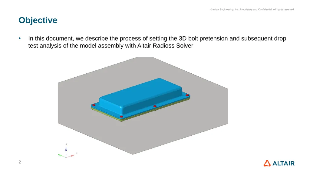
slide2. Objective In this document, we describe the process of setting the 3D bolt pretension and subsequent drop test analysis of the model assembly with Altair Radioss Solver 2<br>
slide3. Contents Setup for 3D bolt pretension with HyperMesh 2020.1 Radioss User Interface (UI)
Analysis workflow
Approaches to perform the sequential analyses
Illustration example
Electronic unity, with bolt pretension and subsequent drop 3<br>
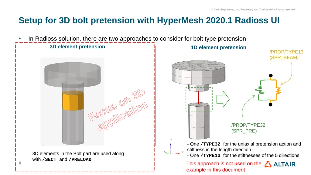
slide4. Setup for 3D bolt pretension with HyperMesh 2020.1 Radioss UI In Radioss solution, there are two approaches to consider for bolt type pretension 4 3D element pretension 1D element pretension This approach is not used on the example in this document /PROP/TYPE32 (SPR_PRE) /PROP/TYPE13 (SPR_BEAM) - One /TYPE32 for the uniaxial pretension action and stiffness in the length direction
- One /TYPE13 for the stiffnesses of the 5 directions 3D elements in the Bolt part are used along with /SECT and /PRELOAD Focus on 3D
application<br>
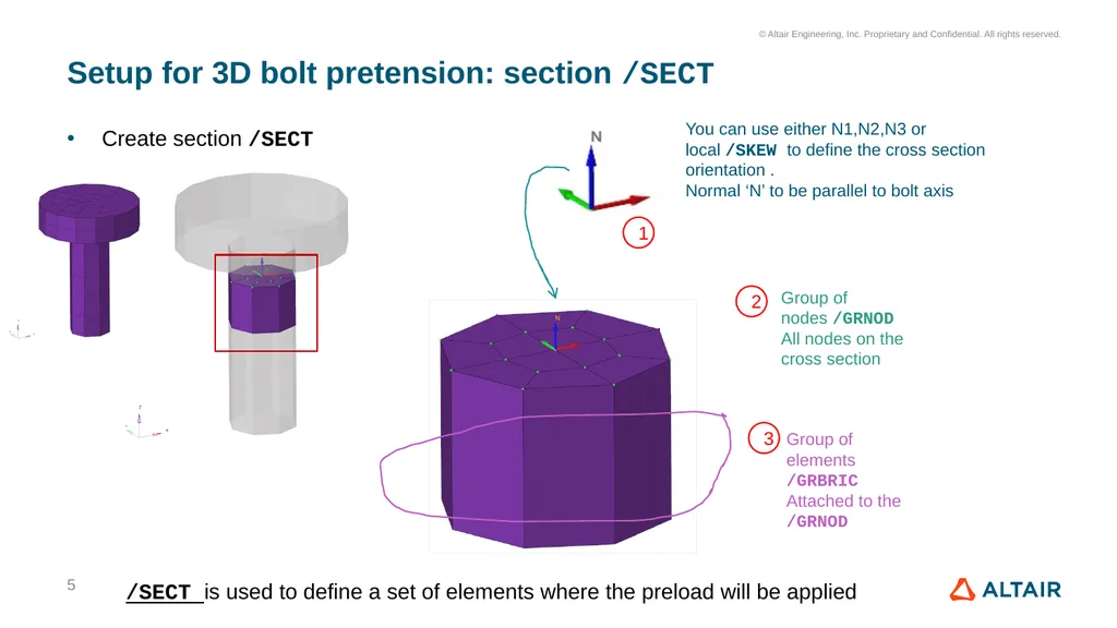
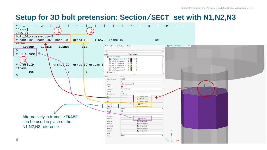
slide5. Setup for 3D bolt pretension: section /SECT Create section /SECT 5 Group of elements /GRBRIC
Attached to the /GRNOD You can use either N1,N2,N3 or local /SKEW to define the cross section orientation .
Normal ‘N’ to be parallel to bolt axis Group of nodes /GRNOD
All nodes on the cross section 1 2 3 /SECT is used to define a set of elements where the preload will be applied<br>
slide6. Setup for 3D bolt pretension: Section/SECT set with N1,N2,N3 6 #---1----|----2----|----3----|----4----|----5----|----6----|----7----|----8----|----9----|---10----|
/SECT/1
bolt_01_crosssection1
# node_ID1 node_ID2 node_ID3 grnod_ID I_SAVE Frame_ID Dt alpha
105809 105818 105805 165 0 0 0 0
# File name
# grbricID grshel_ID grrus_ID grbeam_ID grsprinID grtrianID Ninter Iframe
166 0 0 0 0 0 0 0 1 2 3 Alternatively, a frame /FRAME can be used in place of the N1,N2,N3 reference<br>
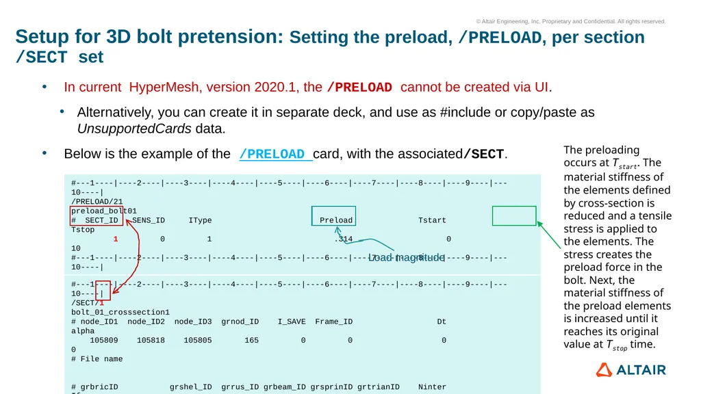
slide7. Setup for 3D bolt pretension: Setting the preload, /PRELOAD, per section /SECT set #---1----|----2----|----3----|----4----|----5----|----6----|----7----|----8----|----9----|---10----|
/PRELOAD/21
preload_bolt01
# SECT_ID SENS_ID IType Preload Tstart Tstop
1 0 1 .314 0 10
#---1----|----2----|----3----|----4----|----5----|----6----|----7----|----8----|----9----|---10----| #---1----|----2----|----3----|----4----|----5----|----6----|----7----|----8----|----9----|---10----|
/SECT/1
bolt_01_crosssection1
# node_ID1 node_ID2 node_ID3 grnod_ID I_SAVE Frame_ID Dt alpha
105809 105818 105805 165 0 0 0 0
# File name
# grbricID grshel_ID grrus_ID grbeam_ID grsprinID grtrianID Ninter Iframe
166 0 0 0 0 0 0 0 In current HyperMesh, version 2020.1, the /PRELOAD cannot be created via UI.
Alternatively, you can create it in separate deck, and use as #include or copy/paste as UnsupportedCards data.
Below is the example of the /PRELOAD card, with the associated/SECT. Load magnitude The preloading occurs at Tstart. The material stiffness of the elements defined by cross-section is reduced and a tensile stress is applied to the elements. The stress creates the preload force in the bolt. Next, the material stiffness of the preload elements is increased until it reaches its original value at Tstop time.<br>
slide8. Setup for 3D bolt pretension: More information on the Preload technique More information on the bolt pretension with Radioss Solver can be found in the documentation:
https://2020.help.altair.com/2020.1/hwsolvers/rad/topics/solvers/rad/preload_intro_c.htm#concept_ujf_bdb_jfb 8<br>
slide9. Remaining Model setup steps The model setting steps for:
Material, properties, contact interactions, rigid wall, output requests
are not described in this document
Tutorials for the creation of these cards can be found in the documentation link below:
https://2020.help.altair.com/2020.1/hwsolvers/rad/topics/chapter_heads/hypermesh_tutorials_r.htm 9<br>
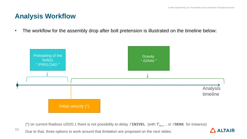
slide10. Analysis Workflow The workflow for the assembly drop after bolt pretension is illustrated on the timeline below: 10 (*) on current Radioss v2020.1 there is not possibility to delay /INIVEL (with TStart , or /SENS for instance)
Due to that, three options to work around that limitation are proposed on the next slides.<br>
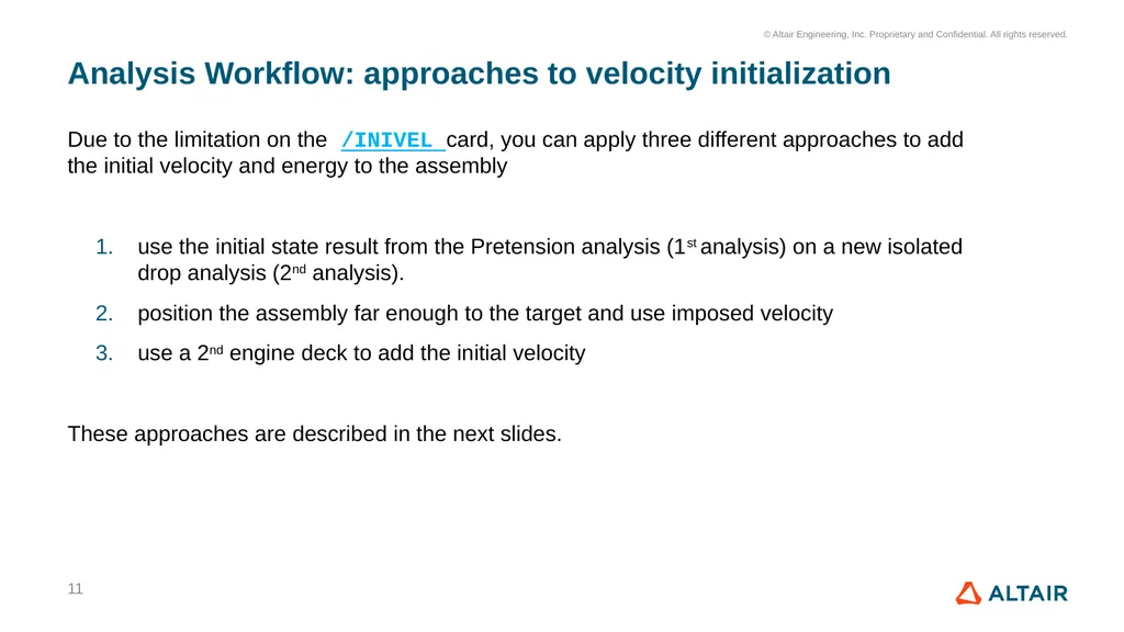
slide11. Analysis Workflow: approaches to velocity initialization Due to the limitation on the /INIVEL card, you can apply three different approaches to add the initial velocity and energy to the assembly
use the initial state result from the Pretension analysis (1st analysis) on a new isolated drop analysis (2nd analysis).
position the assembly far enough to the target and use imposed velocity
use a 2nd engine deck to add the initial velocity
These approaches are described in the next slides. 11<br>
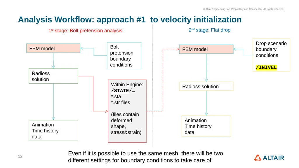
slide12. Analysis Workflow: approach #1 to velocity initialization 12 1st stage: Bolt pretension analysis Radioss
solution Within Engine:
/STATE/…
*.sta
*.str files
(files contain deformed shape, stress&strain) 2nd stage: Flat drop Animation
Time history
data FEM model FEM model Radioss solution Bolt pretension boundary
conditions Drop scenario boundary
conditions
/INIVEL Animation
Time history
data Even if it is possible to use the same mesh, there will be two different settings for boundary conditions to take care of<br>
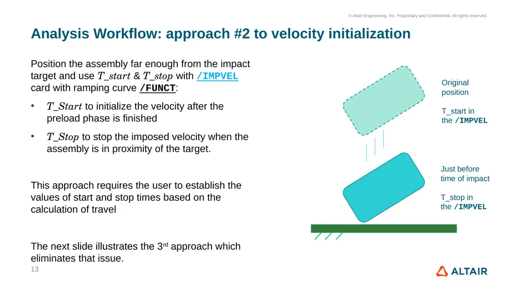
slide13. Analysis Workflow: approach #2 to velocity initialization Position the assembly far enough from the impact target and use T_start & T_stop with /IMPVEL card with ramping curve /FUNCT:
T_Start to initialize the velocity after the preload phase is finished
T_Stop to stop the imposed velocity when the assembly is in proximity of the target.
This approach requires the user to establish the values of start and stop times based on the calculation of travel
The next slide illustrates the 3rd approach which eliminates that issue. 13<br>
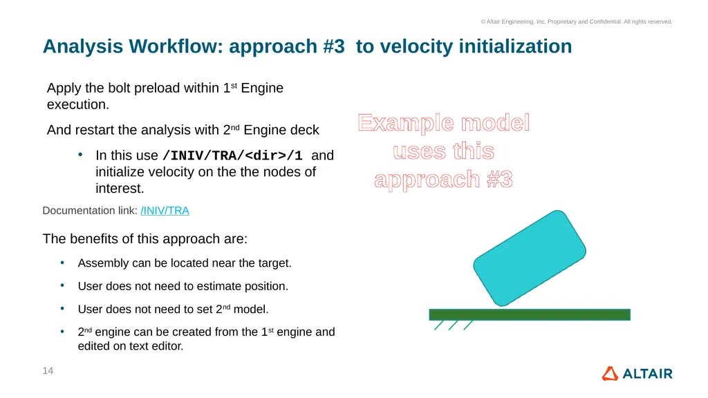
slide14. Analysis Workflow: approach #3 to velocity initialization Apply the bolt preload within 1st Engine execution.
And restart the analysis with 2nd Engine deck
In this use /INIV/TRA/<dir>/1 and initialize velocity on the the nodes of interest.
The benefits of this approach are:
Assembly can be located near the target.
User does not need to estimate position.
User does not need to set 2nd model.
2nd engine can be created from the 1st engine and edited on text editor. 14 Example model uses this approach #3 Documentation link: /INIV/TRA<br>
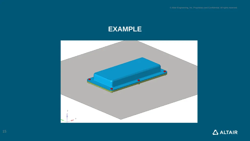
slide15. example 15<br>
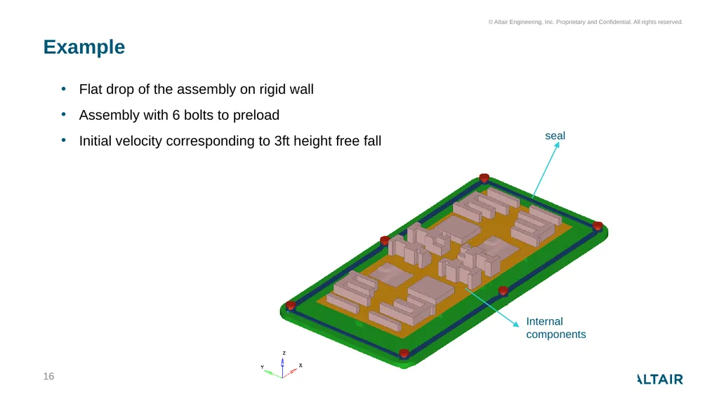
slide16. Example 16 Flat drop of the assembly on rigid wall
Assembly with 6 bolts to preload
Initial velocity corresponding to 3ft height free fall Internal components seal<br>
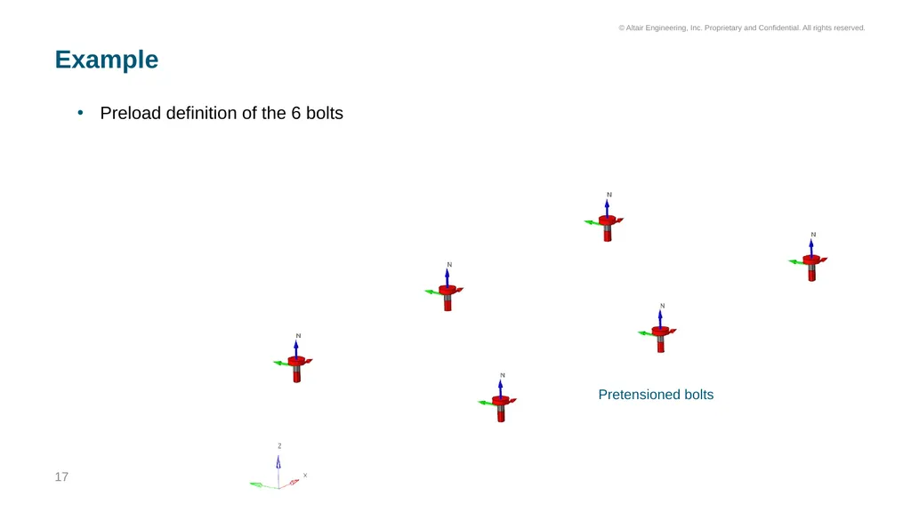
slide17. Example 17 Preload definition of the 6 bolts Pretensioned bolts<br>
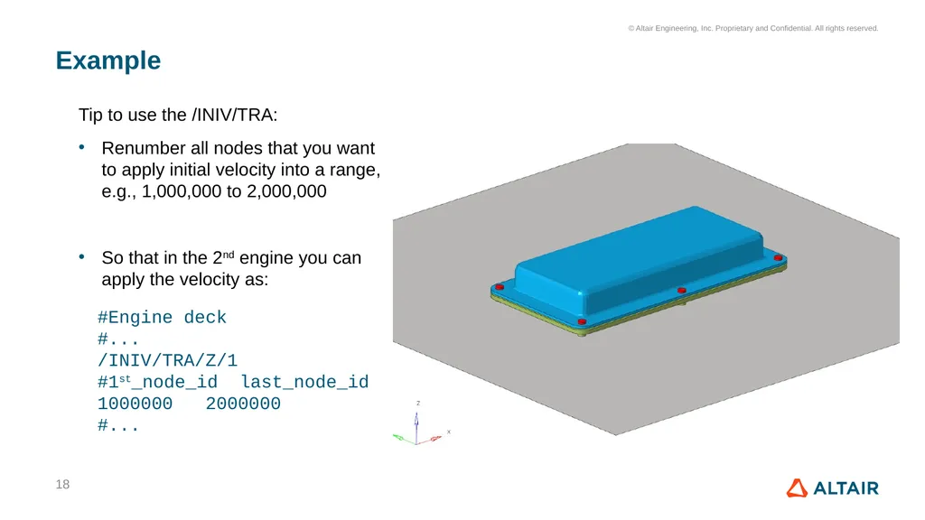
slide18. Example 18 Tip to use the /INIV/TRA:
Renumber all nodes that you want to apply initial velocity into a range, e.g., 1,000,000 to 2,000,000
So that in the 2nd engine you can apply the velocity as: #Engine deck
#...
/INIV/TRA/Z/1
#1st_node_id last_node_id
1000000 2000000
#...<br>
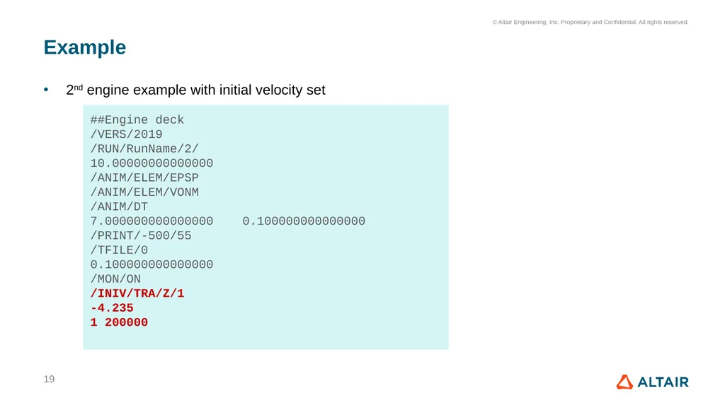
slide19. Example 19 ##Engine deck
/VERS/2019
/RUN/RunName/2/
10.00000000000000
/ANIM/ELEM/EPSP
/ANIM/ELEM/VONM
/ANIM/DT
7.000000000000000 0.100000000000000
/PRINT/-500/55
/TFILE/0
0.100000000000000
/MON/ON
/INIV/TRA/Z/1
-4.235
1 200000 2nd engine example with initial velocity set<br>
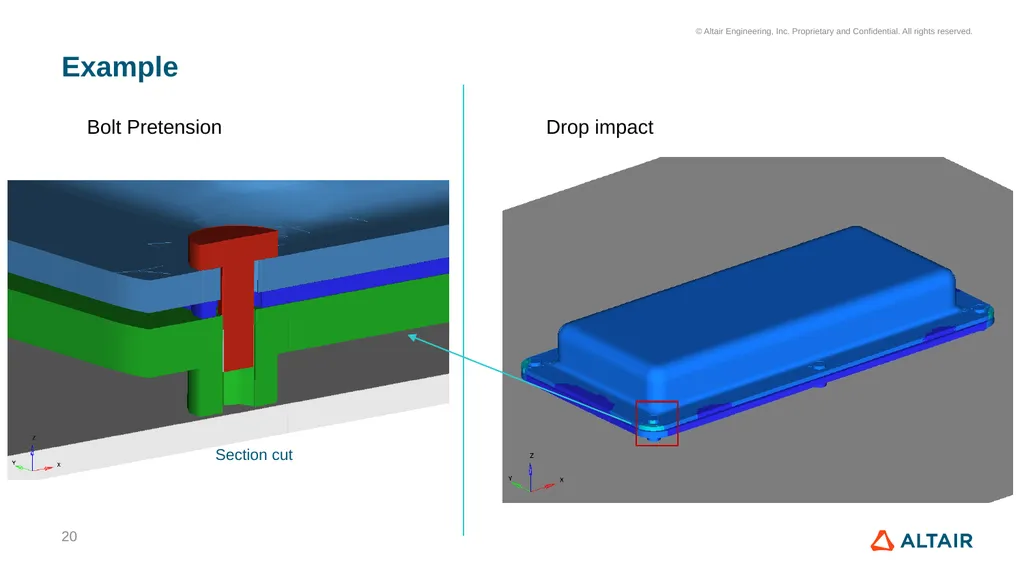
slide20. Example 20 Bolt Pretension Drop impact Section cut<br>
slide21. Example 21<br>
slide2. Objective In this document, we describe the process of setting the 3D bolt pretension and subsequent drop test analysis of the model assembly with Altair Radioss Solver 2<br>
slide3. Contents Setup for 3D bolt pretension with HyperMesh 2020.1 Radioss User Interface (UI)
Analysis workflow
Approaches to perform the sequential analyses
Illustration example
Electronic unity, with bolt pretension and subsequent drop 3<br>
slide4. Setup for 3D bolt pretension with HyperMesh 2020.1 Radioss UI In Radioss solution, there are two approaches to consider for bolt type pretension 4 3D element pretension 1D element pretension This approach is not used on the example in this document /PROP/TYPE32 (SPR_PRE) /PROP/TYPE13 (SPR_BEAM) - One /TYPE32 for the uniaxial pretension action and stiffness in the length direction
- One /TYPE13 for the stiffnesses of the 5 directions 3D elements in the Bolt part are used along with /SECT and /PRELOAD Focus on 3D
application<br>
slide5. Setup for 3D bolt pretension: section /SECT Create section /SECT 5 Group of elements /GRBRIC
Attached to the /GRNOD You can use either N1,N2,N3 or local /SKEW to define the cross section orientation .
Normal ‘N’ to be parallel to bolt axis Group of nodes /GRNOD
All nodes on the cross section 1 2 3 /SECT is used to define a set of elements where the preload will be applied<br>
slide6. Setup for 3D bolt pretension: Section/SECT set with N1,N2,N3 6 #---1----|----2----|----3----|----4----|----5----|----6----|----7----|----8----|----9----|---10----|
/SECT/1
bolt_01_crosssection1
# node_ID1 node_ID2 node_ID3 grnod_ID I_SAVE Frame_ID Dt alpha
105809 105818 105805 165 0 0 0 0
# File name
# grbricID grshel_ID grrus_ID grbeam_ID grsprinID grtrianID Ninter Iframe
166 0 0 0 0 0 0 0 1 2 3 Alternatively, a frame /FRAME can be used in place of the N1,N2,N3 reference<br>
slide7. Setup for 3D bolt pretension: Setting the preload, /PRELOAD, per section /SECT set #---1----|----2----|----3----|----4----|----5----|----6----|----7----|----8----|----9----|---10----|
/PRELOAD/21
preload_bolt01
# SECT_ID SENS_ID IType Preload Tstart Tstop
1 0 1 .314 0 10
#---1----|----2----|----3----|----4----|----5----|----6----|----7----|----8----|----9----|---10----| #---1----|----2----|----3----|----4----|----5----|----6----|----7----|----8----|----9----|---10----|
/SECT/1
bolt_01_crosssection1
# node_ID1 node_ID2 node_ID3 grnod_ID I_SAVE Frame_ID Dt alpha
105809 105818 105805 165 0 0 0 0
# File name
# grbricID grshel_ID grrus_ID grbeam_ID grsprinID grtrianID Ninter Iframe
166 0 0 0 0 0 0 0 In current HyperMesh, version 2020.1, the /PRELOAD cannot be created via UI.
Alternatively, you can create it in separate deck, and use as #include or copy/paste as UnsupportedCards data.
Below is the example of the /PRELOAD card, with the associated/SECT. Load magnitude The preloading occurs at Tstart. The material stiffness of the elements defined by cross-section is reduced and a tensile stress is applied to the elements. The stress creates the preload force in the bolt. Next, the material stiffness of the preload elements is increased until it reaches its original value at Tstop time.<br>
slide8. Setup for 3D bolt pretension: More information on the Preload technique More information on the bolt pretension with Radioss Solver can be found in the documentation:
https://2020.help.altair.com/2020.1/hwsolvers/rad/topics/solvers/rad/preload_intro_c.htm#concept_ujf_bdb_jfb 8<br>
slide9. Remaining Model setup steps The model setting steps for:
Material, properties, contact interactions, rigid wall, output requests
are not described in this document
Tutorials for the creation of these cards can be found in the documentation link below:
https://2020.help.altair.com/2020.1/hwsolvers/rad/topics/chapter_heads/hypermesh_tutorials_r.htm 9<br>
slide10. Analysis Workflow The workflow for the assembly drop after bolt pretension is illustrated on the timeline below: 10 (*) on current Radioss v2020.1 there is not possibility to delay /INIVEL (with TStart , or /SENS for instance)
Due to that, three options to work around that limitation are proposed on the next slides.<br>
slide11. Analysis Workflow: approaches to velocity initialization Due to the limitation on the /INIVEL card, you can apply three different approaches to add the initial velocity and energy to the assembly
use the initial state result from the Pretension analysis (1st analysis) on a new isolated drop analysis (2nd analysis).
position the assembly far enough to the target and use imposed velocity
use a 2nd engine deck to add the initial velocity
These approaches are described in the next slides. 11<br>
slide12. Analysis Workflow: approach #1 to velocity initialization 12 1st stage: Bolt pretension analysis Radioss
solution Within Engine:
/STATE/…
*.sta
*.str files
(files contain deformed shape, stress&strain) 2nd stage: Flat drop Animation
Time history
data FEM model FEM model Radioss solution Bolt pretension boundary
conditions Drop scenario boundary
conditions
/INIVEL Animation
Time history
data Even if it is possible to use the same mesh, there will be two different settings for boundary conditions to take care of<br>
slide13. Analysis Workflow: approach #2 to velocity initialization Position the assembly far enough from the impact target and use T_start & T_stop with /IMPVEL card with ramping curve /FUNCT:
T_Start to initialize the velocity after the preload phase is finished
T_Stop to stop the imposed velocity when the assembly is in proximity of the target.
This approach requires the user to establish the values of start and stop times based on the calculation of travel
The next slide illustrates the 3rd approach which eliminates that issue. 13<br>
slide14. Analysis Workflow: approach #3 to velocity initialization Apply the bolt preload within 1st Engine execution.
And restart the analysis with 2nd Engine deck
In this use /INIV/TRA/<dir>/1 and initialize velocity on the the nodes of interest.
The benefits of this approach are:
Assembly can be located near the target.
User does not need to estimate position.
User does not need to set 2nd model.
2nd engine can be created from the 1st engine and edited on text editor. 14 Example model uses this approach #3 Documentation link: /INIV/TRA<br>
slide15. example 15<br>
slide16. Example 16 Flat drop of the assembly on rigid wall
Assembly with 6 bolts to preload
Initial velocity corresponding to 3ft height free fall Internal components seal<br>
slide17. Example 17 Preload definition of the 6 bolts Pretensioned bolts<br>
slide18. Example 18 Tip to use the /INIV/TRA:
Renumber all nodes that you want to apply initial velocity into a range, e.g., 1,000,000 to 2,000,000
So that in the 2nd engine you can apply the velocity as: #Engine deck
#...
/INIV/TRA/Z/1
#1st_node_id last_node_id
1000000 2000000
#...<br>
slide19. Example 19 ##Engine deck
/VERS/2019
/RUN/RunName/2/
10.00000000000000
/ANIM/ELEM/EPSP
/ANIM/ELEM/VONM
/ANIM/DT
7.000000000000000 0.100000000000000
/PRINT/-500/55
/TFILE/0
0.100000000000000
/MON/ON
/INIV/TRA/Z/1
-4.235
1 200000 2nd engine example with initial velocity set<br>
slide20. Example 20 Bolt Pretension Drop impact Section cut<br>
slide21. Example 21<br>