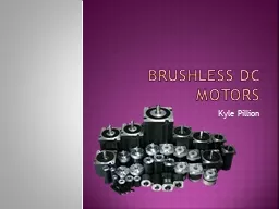
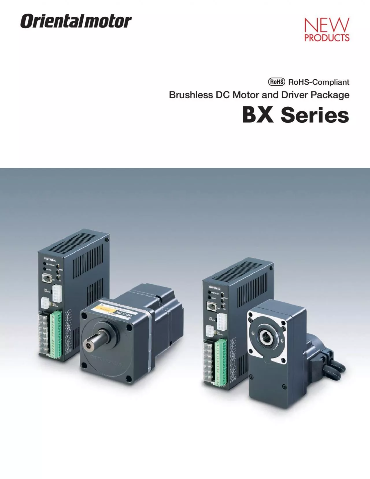
/
BX Series brushless DC motor and driver packages offer high performanc BX Series brushless DC motor and driver packages offer high performanc

BX Series brushless DC motor and driver packages offer high performanc - PDF document

winnie
winnie . @winnie
Follow
342 views
Uploaded On 2022-08-20

BX Series brushless DC motor and driver packages offer high performanc - PPT Presentation

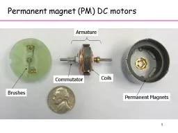
2 Series WLoad 0300100020003000 Starting Torque MotorDriver 3Digital Speed Setting Up to eight speedsSpeed can be set digitally using an optional control module You can set up to eight different ID: 938577

100 motor input shaft motor 100 shaft input speed phase power type control 230 supply 400 gearhead vac output

Share:

Link:

Embed:

Download Presentation from below link

Download Pdf The PPT/PDF document "BX Series brushless DC motor and driver ..." is the property of its rightful owner. Permission is granted to download and print the materials on this web site for personal, non-commercial use only, and to display it on your personal computer provided you do not modify the materials and that you retain all copyright notices contained in the materials. By downloading content from our website, you accept the terms of this agreement.


Presentation Transcript

2 Series BX Series brushless DC motor and driver packages offer high performance and high function. BX Series provides the torque limiting, position control and other extended WLoad 0300100020003000 Starting Torque MotorDriver 3Digital Speed Setting (Up to eight speeds)Speed can be set digitally using an optional control module. You can set up to eight different speed. Tension Combination Type–Parallel Shaft Gearhead, Round Shaft Type Combination Type(Motor/Gearhead) Combination Type SOL4M6MCL5515F10 ADP01 Flexible CouplingDIN RailMounting Plate CC01SBFExtension Cable(1 m [3.3 ft]) A flexible extension cable is available for BX Series. It is most

suitable for uses where the cable is bent or twisted. ( Page 43) Controller PowerSupply : Optional accessory offered by Oriental Motor. The system configuration shown above is an example. Other combinations are available. Combination Type–Hollow Shaft Flat Gearhead Combination Type ADP01 DIN RailMounting Plate CC01SBFExtension Cable(1 m [3.3 ft]) Series Combination Type Controller PowerSupplyDIN Rail Mounting Plate (Accessories)Driver can be snapped into DIN rails. ( Regeneration Unit (Accessories)Regenerated energy is discharged during a vertical ( Page 44)Example of System Configuration(Sold separately)External Speed Potentiometer : Optional

accessory offered by Oriental Motor. The system configuration shown above is an example. Other combinations are available.Safety Standards and CE Marking ModelStandardsCerti cation BodyStandards File No.CE MarkingULE171462EN 50178Conform to EN/IEC Standards 6Product Number Code BX 2 30 A M - 5 FR werty : 104 mm (4.09 in.) [Gearhead Frame Size: Output Power (W)(Example) : Single-Phase 100–115 VAC: Single-Phase, Three-Phase 200–230 VAC: Three-Phase 200–230 VAC: Electromagnetic Brake Type: Pinion Shaft Type: Combination Type–Parallel Shaft Gearhead: Combination Type–Hollow Shaft Flat Gearhead This simplifies installation in equipment. Motors an

d gearheads are also available separately to facilitate changes or repairs.Combination Type–Parallel Shaft Gearhead ModelGear Ratio100–115 VAC200–230 VAC100–115 VAC200–230 VAC100–115 VAC200–230 VAC100–115 VAC200–230 VAC200–230 VACCombination Type–Hollow Shaft Flat Gearhead ModelGear Ratio100–115 VAC200–230 VAC100–115 VAC200–230 VAC100–115 VAC200–230 VAC Output PowerPower Supply VoltageModel Output PowerPower Supply VoltageModelSingle-Phase 100–115 VAC200–230 VACSingle-Phase 100–115 VAC200–230 VACSingle-Phase 100–115 VAC200–230 VACSingle-Phase 100–115 VAC200–230 VACThree-Phase 200–230 VAC 8SpecificationsStandard30 W (1/25 HP), 60 W (1/12 HP) Com

bination Type–Parallel Shaft GearheadCombination Type–Hollow Shaft Flat GearheadFRBX230C-FRBX460A-FRBX460C-BX230A-ABX230C-ABX460A-ABX460C-ARated Output Power (Continuous)W (HP)30 (1/25)60 (1/12)SourceRated VoltageVAC100–115200–230100–115200–230Rated FrequencyHz50/60Rated Input CurrentA1.4Maximum Input CurrentA2.4Rated TorqueN·m (oz-in)0.1 (14.2)0.2 (28)Starting Torque0.2 (28)0.4 (56)Rated Speedr/minSpeed Control Ranger/minfor Round Shaft Type1.5 (8.2)3 (16.4)0.088 (0.48)0.194 (1.06)0.194 (1.06)32122F], at rated speed, with no load, at rated voltage)1 The starting torque can be used for a maximum duration of approximately 5 seconds at 2000 r/min

or less. 2 This specification applies when a control module Combination Type–Parallel Shaft GearheadCombination Type–Hollow Shaft Flat GearheadFRBX5120C-BX5120A-ABX5120C-ABX6200A-ABX6200C-ABX6400S-ARated Output Power (Continuous)W (HP)120 (1/6)200 (1/4)400 (1/2)SourceRated VoltageVAC100–115200–230100–115200–230200–230Rated FrequencyHz50/60Rated Input CurrentA3.7Maximum Input CurrentA6.7Rated TorqueN·m (oz-in)0.4 (56)0.65 (92)1.3 (184)Starting Torque0.8 (113)1.3 (184)2.6 (360)Rated Speedr/minSpeed Control Ranger/minfor Round Shaft Type (33)10 (55)17.5 (96)0.625 (3.4)0.66 (3.6)0.66 (3.6)0.66 (3.6)32122F], at rated speed, with no load, at rated vo

ltage)1 The starting torque can be used for a maximum duration of approximately 5 seconds at 2000 r/min or less. 2 This specification applies when a control module 10Common Specifications ItemSpeci cations· Overvoltage protection (3): Maximum Extended Length20.4 m (67.3 ft) between the motor and driver (when an accessory extension cable is used)ime RatingContinuous The input signals and output signals may function differently when the control module is used. ItemMotorDriverSuf cient to withstand 1.5 kVAC at 50 Hz applied between the Suf cient to withstand 1.5 kVAC at 50 Hz applied between the case and Ambient Temperatureemperature32122

F] (non-freezing)Ambient Humidity85% max. (non-condensing)AltitudeUp to 1000 m (3300 ft) above sea levelAtmosphereNo corrosive gases or dust. Use in a radioactive or magnetic  Ambient Temperatureemperature4140F] (non-freezing)2570C [13158F] (non-freezing)Ambient Humidity85% max. (non-condensing)AltitudeUp to 3000 m (10000 ft) above sea levelUp to 3000 m (10000 ft) above sea levelF] ), EN standards: class E (120C [248F])Degree of ProtectionIP54 (Excluding the mounting surface of the round shaft type and the connector)IP101 For round shaft types, please attach to the heat radiation plate (material: aluminum) of the following sizes to

maintain a ma4.53 in.), 5 mm (0.20 in.) thick 6.50 in.), 5 mm (0.20 in.) thick 12Return to Electrical Home Operation ItemSpeci cationsTravel AmountFrom the current motor position to the electrical home positionInitial Offset Value0Speed Control Range3 ItemSpeci cationsGearmotor–Torque Table of Combination TypeCombination Type–Parallel Shaft Gearhead 51015203050100200 -SBX230 M-S0.45(3.9)0.9(7.9)1.4(12.3)1.8(15.9)2.6(23)4.3(38)6(53)6(53)BX460 -SBX460 M-S0.9(7.9)1.8(15.9)2.7(23)3.6(31)5.2(46)8.6(76)16(141)16(141)BX5120 -SBX5120 M-S1.8(15.9)3.6(31)5.4(47)7.2(63)10.3(91)17.2(152)30(260)30(260)BX6200 -SBX6200 M-S2.9(25)5.9(52)8.8(77)11.7(10

3)16.8(148)28(240)52.7(460)70(610)BX6400S-SBX6400SM-S5.9(52)11.7(103)17.6(155)23.4(207)33.5(290)55.9(490)70(610)70(610)Values in parentheses only apply when a control module OPX-1A is used. Enter the power supply voltage (A or C) in the box ( Combination Type–Hollow Shaft Flat Gearhead 51015203050100200 -FRBX230 M-FR0.4(3.5)0.85(7.5)1.3(11.5)1.7(15.0)2.6(23)4.3(38)8.5(75)1.7(150)BX460 -FRBX460 M-FR0.85(7.5)1.7(15.0)2.6(23)3.4(30)5.1(45)8.5(75)17(150)3.4(300)BX5120 -FRBX5120 M-FR1.7(15.0)3.4(30)5.1(45)6.8(6.0)10.2(90)17(150)34(300)6.8(600)Values in parentheses only apply when a control module OPX-1A is used. Enter the power supply voltage (A

or C) in the box ( ) within the model name. Enter the gear ratio in the box () within the model name. The flat gearhead rotates in the opposite direction to the motor when viewed from the front of the gearhead. It rotates in the same direction as the motor when viewed from the rear (motor mounting surface) of the gearhead. Rotation direction of the hollow shaft flat gearhead  Page 14 -SBX460 M-S2.210-3(120)9.510-3(520)2.210-2(1200)3.510-2(1910)810-2(4400)2.210-1(12000)6.210-1(34000)1.2(66000)When quick stop or instantaneous bi-directional motion is used10-4(30)2210-4(120)49.510-4(270)8810-4(480)19810-4(1080)55010-4(3000)55010-4(300

0)55010-4(3000)BX5120 -SBX5120 M-S4.510-3(250)1.910-2(1040)4.210-2(2300)710-2(3800)1.610-1(8800)4.510-1(25000)1.2(66000)2.5(137000)When quick stop or instantaneous bi-directional motion is used10-4(137)10010-4(550)22510-4(1230)40010-4(2200)90010-4(4900)250010-4(13700)250010-4(13700)250010-4(13700)BX6200 -SBX6200 M-S110-2(550)4.610-2(2500)110-1(5500)1.710-1 51015203050100200 -FRBX230 M-FR1.210-3(66)510-3(270)1.110-2(600)210-2(1090)3.710-2(2000)9.210-2(5000)2.510-1(13700)510-1(27000)When quick stop or instantaneous bi-directional motion is used10-4(8.5)6.210-4(34)1410-4(77)24.810-4(136)55.810-4(310)15510-4(850)155

10-4(850)15510-4(850)BX460 -FRBX460 M-FR2.210-3(120)9.510-3(520)2.210-2(1200)3.510-2(1910)810-2(4400)2.210-1(12000)6.210-1(34000)1.2(66000)When quick stop or instantaneous bi-directional motion is used10-4(30)2210-4(120)49.510-4(270)8810-4(480)19810-4(1080)55010-4(3000)55010-4(3000)55010-4(3000)BX5120 -FRBX5120 M-FR4.510-3(250)1.910-2(1040)4.210-2(2300)710-2(3800)1.610-1(8800)4.510-1(25000)1.2(66000)2.5(137000)When quick stop or instantaneous When the CWinput is ON.When the CCWinput is ON.Front View When the CWinput is ON.When the CCWinput is ON.Rear View Speed–Torque CharacteristicsContinuous Duty Region: Continuous operati

on is possible in this region.Limited Duty Region: /BX230 S/BX230 FRBX230 /BX230 S/BX230 FR 0.20 30(3)100020003000 02025 10155 BX460 /BX460 S/BX460 FRBX460 /BX460 S/BX460 FR 0.30.2 0.40 30(3)100020003000 010203040 50 BX5120 /BX5120 S/BX5120 FRBX5120 /BX5120 S/BX5120 FR 0.4 0.2 0.6 100020003000 Starting Torque Torque [N·m]Torque [oz-in] 020406080 100 BX6200 /BX6200 SBX6200 /BX6200 S 30(3)100020003000 1.3 0.65 0.5 1.5 20 Continuous Duty RegionLimited Duty RegionTorque [N·m]Torque [oz-in] 150 100 200 2500 50 BX6400S-A/BX6400S-SBX6400SM-A/BX6400SM-S 30(3)100020003000 1.3 2.6 1 30 Continuous Duty RegionLimited Duty RegionTorque [N·m]T

orque [oz-in] 0200100300 400 Values in parentheses only apply when a control module OPX-1A is used. The characteristics shown above apply to the motor only. Enter the power supply voltage (A or C) in the box ( ) within the model name.Enter the gear ratio in the box () within the model name. 17Enter the gear ratio in the box () within the model name.Motor/Hollow Shaft Flat GearheadBX230A-FR, BX230C-FRMotor: BXM230-GFSGearhead: GFS2GFRMass: 1.5 kg (3.3 lb) Including gearhead 0.82 9(0.35, 400 mm ( in. LengthHousing: 5557-10R (MOLEX)Encoder Cable 8 (0.31, 400 mm ( in. LengthHousing: 5557-06R (MOLEX)Round Terminal: SRA-51T-4 (JST)340.039045

.5 (0.217 Thru11(0.43) 49(1.93)148(0.31)8(0.31) (8)(1.02)(2.78)(0.03)1.33860.0015700.5(2.760.02)40 0.0400.15750 0.00161.22) 0.20.03 0.15750.001200.9840.008) 0.03 00.15750.00120.05)(0.55)(0.55)(0.05)1.151.15 12.5 0.4921 0.110.00430.00110.02712 0 0.4724 12.5 0.4921 0.110.00430.00110.02712 0 0.4724 19Enter the gear ratio in the box () within the model name.Motor/Hollow Shaft Flat GearheadBX460A-FR, BX460C-FRMotor: BXM460-GFSGearhead: GFS4GFRMass: 2.6 kg (5.7 lb) Including gearhead (3.15)153.2(2.09)79.5(3.13)80(3.15)160.5(6.32)80.5(3.17)AA80(3.15) 8 (0.31, 400 mm ( in. LengthHousing: 5557-10R (MOLEX)Ho

using: 5557-06R (MOLEX)54(2.136.5 (0.256 Thru (0.71) (0.71) (2.17)  0.03 00.19690.0012 0.20.9840.008)2671.51.5(0.06)8(0.31)45.2(1.02)(2.81)3(0.12)4(0.16) 0.04) 380.039001.49610.00150.9825 9(0.35, 400 mm ( in. Length200(8) (0.68) 1.22) 0 0.0400.19690 0.0016(0.43) 0.5(3.700.02) 0.00110.02715 0 0.5906 15.7 0.6181 0.110.00430.00110.02715 0 0.5906 (0.39)10(0.39) 0.05)1.15 0.05)1.1515.7 0.6181 0.110.00430.03 0.19690.00120(JST) Round Shaft TypeBX460A-A, BX460C-AMotor: BXM460-A2Mass: 1.0 kg (2.2 lb) (0.37)80(3.15)54(2.1371.5(2.81) 00730.030 (2.87400.0012100.015 (0.39370.00060080(3.15 8 (0.31,

400 mm ( in. LengthHousing: 5557-10R (MOLEX)Round Terminal: SRA-51T-4 (JST)Housing: 5557-06R (MOLEX)Motor Cable 9(0.35, 400 mm ( in. Length46.5 (0.256 Thru (0.43) (1.02) (0.31)(0.08) 1(1.260.04) (0.98) 0.5(3.700.02) (1.22)200(8) 21Enter the gear ratio in the box () within the model name.Round Shaft TypeBX5120A-A, BX5120C-AMotor: BXM5120-A2Mass: 1.6 kg (3.5 lb) 11.5(90(11(83(37120010 120.0180830.035090Motor Cable 9(0.35, 400 mm(in. Length Encoder Cable 8(0.31, 400 mm(in. LengthHousing: 5557-10R (MOLEX)Housing: 5557-06R (MOLEX)Round Terminal: SRA-51T-4 (JST)1040.5((( 8.5(0.335Thru54(2.13(1.46(4.090.023.54 3.26770.0014 0.4724

0.0007 Standard Type 200 W (1/4 HP), 400 W (1/2 HP)Motor/Parallel Shaft Gearhead ModelMotor ModelGearhead ModelGear RatioLCAD A1026108(32350.550124.5((L 0.5104(4.09110(4.3312(Deep1200.5 Housing: 5557-10R (MOLEX)Housing: 5557-06R (MOLEX) 220.0210 0 (The key is included with the geahead. At the time of shipment, Motor Cable 9(0.35, 400 mm(in. LengthEncoder Cable 8(0.31, 400 mm(in. Length104(11(54(2.13(((1.380.02(1.970.040.86610.0008(4.720.0248.5(0.335Thru42(1.6525(0.790.02 0.03 0 0.23620.0012 0.7280.004 0.03 0 0.23620.00121.2600.0080.980.231 23Enter the gear ratio in the box () within the model name.Motor/Hollow Shaft Flat Ge

arheadBX230AM-FR, BX230CM-FRMotor: BXM230M-GFSGearhead: GFS2GFRMass: 1.8 kg (4.0 lb) Including gearhead A110(4.33)54(2.1360(2.36)59.5(2.34)60.5(2.38)47.8(1.88)1.5(0.06)60(2.36) 8 (0.31, 400 mm ( in. LengthHousing: 5557-10R (MOLEX)Round Terminal: SRA-51T-4 (JST)Housing: 5557-06R (MOLEX) 0.20.03 0.15750.001200.9840.008) 0.03 00.15750.0012200(8)0.8 0.03)2(0.08)3(0.12) 340.039001.33860.00150.7920 0 0.0400.15750 0.0016 5.5 (0.217 Thru13.860(2.36)31(0.54)120.5(4.74) (0.43) 1.22) 268 1.02)39.8 1.57) 9(0.35, 400 mm ( in. Length 49(1.93)148(0.31)8(0.31) 0.05)(0.55)(0.55)(0.05)1.151.15 12.5 0.4921 0.110.00430.00110.02712 0

0.4724 12.5 0.4921 0.110.00430.00110.02712 0 0.4724 Round Shaft TypeBX230AM-A, BX230CM-AMotor: BXM230M-A2Mass: 1.0 kg (2.2 lb) (2.36)11(0.43) 54(2.13(4.33) Housing: 5557-10R (MOLEX)Round Terminal: SRA-51T-4 (JST)Housing: 5557-06R (MOLEX)Encoder Cable 8 (0.31, 400 mm ( in. Length (1.22) 4.5 (0.177 Thru700.5(2.760.02) 8(0.31)(0.08)26(1.02) (0.3) (0.63) 241(0.950.04)6080.015 (0.31500.00060000540.030 (2.12600.00122.36 9(0.35, 400 mm ( in. Length200(8) 25Enter the gear ratio in the box () within the model name.Motor/Hollow Shaft Flat GearheadBX460AM-FR, BX460CM-FRMotor: BXM460M-GFSGearhead: GFS4GFRMass: 3.1 kg

(6.8 lb) Including gearhead (2.09)79.5(3.13)80.5(3.17)80(3.15)1.5(0.06)107.5AA2625 8 (0.31, 400 mm ( in. LengthHousing: 5557-10R (MOLEX)Round Terminal: SRA-51T-4 (JST)Housing: 5557-06R (MOLEX)54(2.13  9(0.35, 400 mm ( in. Length200(8)1 (0.12)4(0.16) 0.04) 380.039001.49610.00150.98 (0.31)(1.02)45.2(4.23) (3.15)80(3.15)160.5(6.32) 6.5 (0.256 Thru (0.68) 1.22) 0 0.0400.19690 0.0016(0.43) 0.5(3.700.02) (0.71) (0.71) (2.17) 0.00110.02715 0 0.5906 15.7 0.6181 0.110.00430.00110.02715 0 0.5906 (0.39)10(0.39) 0.05)1.15 0.05)1.1515.7 0.6181 0.110.0043 0.03 00.19690.0012 0.20.9840.008)50.03 0.19690.001

20 Round Shaft TypeBX460AM-A, BX460CM-AMotor: BXM460M-A2Mass: 1.5 kg (3.3 lb) (3.15)11(0.43) 107.5(4.23) 54(2.13 8 (0.31, 400 mm ( in. LengthHousing: 5557-10R (MOLEX)Round Terminal: SRA-51T-4 (JST)Housing: 5557-06R (MOLEX)200(8) 9(0.35, 400 mm ( in. Length 6.5 (0.256 Thru940.5(3.70 (1.22)26 1.02) (0.31)(0.08)9.5(0.37) 0730.030 (2.87400.0012100.015 (0.39370.00060080(3.15 1(1.260.04) (0.98) 27Enter the gear ratio in the box () within the model name.Motor/Hollow Shaft Flat GearheadBX5120AM-FR, BX5120CM-FRMotor: BXM5120M-GFSGearhead: GFS5GFRMass: 4.4 kg (9.7 lb) Including gearhead 119102AA5426200 Housing: 5557-10R (MOLEX) Round Te

rminal: SRA-51T-4 (JST)Housing: 5557-06R (MOLEX) ( 9(0.35, 400 mm(in. LengthEncoder Cable 8(0.31, 400 mm(in. Length ( (13(( (22( 21 0.2121 0.2120 0.03320 0.033 0.78740 0.0013 0.78740 0.0013 0.82680 0.0083 0.82680 0.0083( 0.20.03 00.03 00.23620.0012 0.23620.00120.9840.008 22.8311190180 0.548.5(0.335Thru6 00.040 0.23620 0.00164.090.02((((( (90((((((65.2431 30500.0390 1.96850.0015(((((1.181(2.13 29Enter the gear ratio in the box () within the model name.Round Shaft TypeBX6200AM-A, BX6200CM-A, BX6400SM-AMotor: BXM6200M-A, BXM6400M-AMass: 3.5 kg (7.7 lb) 3711026150( Housing: 555

7-10R (MOLEX)Housing: 5557-06R (MOLEX) Motor Cable 9(0.35, 400 mm(in. LengthEncoder Cable 8(0.31, 400 mm(in. Length (11(54(2.13(((1.460.0413((4.09 104140.0180940.0350 0.55120.0007 3.70080.0014 0.54.720.0248.5(0.335Thru Driver (Common to all models)BXD30A-A, BXD30A-C, BXD60A-A, BXD60A-CBXD120A-A, BXD120A-C, BXD200A-A, BXD200A-C, BXD400A-SMass: 0.8 kg (1.8 lb) (10175140(150(1814130(1089(3516( max.5( max.236.2(7.62((120(7M3 7M3176(2M3 Protective EarthTerminal M4 ((((10((((5(( External Speed Potentiometer (Included) 153Screw)KnobDial PlateInsulated SheetPotentiometer 40(7.512.540(0.2 9.50.230(min.M46 Recommended thickness of a mount

ing plate is a maximum 4.5 mm (in.40(1.57 t=0.5(40(1.57 t=0.5(((((((((0.0080.008 Mounting Bracket (2 pieces included) (25252(Countersink(10(4.5( 3( 43((( 31 Speed Control 23CN4 OFFONOFFONOFFOFFONONOFFON L(L2)N(L3) RGRGNC N L1L2L3Single-Phase 100-115 VAC InputSingle-Phase 200-230 VAC Input NC L1L2L3Three-Phase 200-230 VAC Input To Power To Power SupplyTo Power Supply CW InputCCW InputM0 InputM1 InputM2 InputFREE InputBRAKE InputIN-COMM InputH InputL InputALM OutputBUSY OutputASG OutputBSG OutputOUT-COMAnalog InputON :CW StartOFF:StopON :CCW StartOFF:StopON :Motor Excitation CanceledOFF:Motor Operation EnabledON :OperationAlarm Output : [OFF] whe

n OutputBusy Output : [ON] when motor is operatingSpeed Output ASGSpeed Output BSGGNDON :External Speed PotentiometerOFF:Internal Speed PotentiometerConnect the external speed potentiometer (included) or external DC Voltage.When operating motor, BRAKE input should be turned “ON.”Shield WirePower Supply VoltageSingle-phase 100-115 VAC 1510%, 50/60 Hz (Single-phase 100-115 VAC input driver)1510%, 50/60 Hz Or, 1510%, 50/60 Hz (Single-phase/Three-phase 200-230 VAC input driver)ConnectorCN2ConnectorCN3Motor CableEncoder CableProtective Earth Terminal (PE)Terminal Block for Regeneration UnitTerminal Block for Power-Supply InputMotor CableEncode

r CableProtective Earth Terminal (PE)2345678910111213141516 When Using a Control Module 23CN4 GND OFFONOFFONOFFOFFONONOFFONOFFON N(L3) NC(L1) RGRGNC OFF OFF:StopON :CCW StartOFF:StopON :Motor Excitation CanceledOFF:Motor Operation EnabledON :OperationAlarm Output: [OFF] when OutputBusy Output: [ON] when motor is operatingSpeed Output ASGSpeed Output BSGSpeed Data Selection InputConnect the external speed potentiometer(included) or external DC Voltage.When operating motor, BRAKE input should be turned “ON.”Shield WireCW InputCCW InputM0 InputM1 InputM2 InputFREE InputBRAKE InputIN-COMM InputH InputL InputALM OutputBUSY OutputASG OutputBSG OutputO

UT-COMAnalog InputConnectorConnectorCN3ConnectorCN1Control ModuleEncoder CableMotor CableProtective Earth Terminal (PE)Terminal Block for Regeneration UnitTerminal Block for Power-Supply Input N L1L2L3Single-Phase 100-115 VAC InputSingle-Phase 200-230 VAC Input NC L1L2L3Three-Phase 200-230 VAC Input To Power To Power SupplyTo Power Supply Power Supply VoltageSingle-phase 100-115 VAC 1510%, 50/60 Hz (Single-phase 100-115 VAC input driver) 1510%, 50/60 Hz Or,15(Single-phase/Three-phase 200-230 VAC input driver)Motor CableEncoder CableProtective Earth Terminal (PE) 2345678910111213141516 (2) or thicker] Single-Phase 200-230 VAC, 3-core cable [AWG

18 (0.75 mm2) or thicker] Three-Phase 200-230 VAC, 4-core cable [AWG18 (0.75 mm2) or thicker]When wiring the control I/O signal lines, keep a minimum distance of 300 mm from power lines (AC line, motor line and other largecurrent circuits). Also, do not route the control I/O signal lines in the same duct or piping as that is used for power lines.Cables for the power supply lines and control I/O signal lines are not supplied with the product. Provide appropriate cables separately.When grounding the driver, connect the ground wire to the protective earth terminal (M4) and connect the other end to a single point using a cable with a size of AWG18 (0.7

5 mm2) or thicker. I/O Terminals (CN4)When using a crimp terminal for connection, use one of the terminals listed below. The applicable crimp terminal varies, depending on the wire size.When the following terminals are used, the applicable wire size will be between AWG26 and 18 (0.14 to 0.75 mm2).Manufacturer: Phoenix ContactAl 0.25-6 Applicable wire size: AWG26 to 24 (0.14 to 0.2 mmAl 0.5-6 Applicable wire size: AWG20 (0.5 mmAl 0.34-6 Applicable wire size: AWG22 (0.3 mmAl 0.75-6 Applicable wire size: AWG18 (0.75 mm 3.2 mm 0.13 in.) 9 mm0.35 in.) 6.2 mm0.24 in.) 33 Speed Control CW InputBRAKE InputMotorONONON : OperationOFF: Instantaneous StopM0 I

nputONON : External Analog SettingOFF: Internal Speed PotentiometerInternal Speed PotentiometerExternal Analog SettingONInstantaneous StopONSpeed DataInternal Speed PotentiometerExternal Analog Setting Switching to a lower speed using the M0 input while the motor is operating will cause the motor to decelerate over the time set by the acceleration time potentiometer, not the time set by the deceleration time potentiometer.Motor Control Release (FREE) InputWhen the photocoupler is turned ON, the motor excitation is cancelled and the electromagnetic brake is released. The FREE  Brake (BRAKE)/Alarm Reset (ALARM-RESET) InputThis input functions as the B

RAKE input during normal operation, and as the ALARM-RESET input when a driver protective function During Normal Operation (BRAKE Input)When the BRAKE input is turned ON, motor operation is enabled. If it is turned OFF, the motor is stopped instantaneously. To start StopCW OperationCW InputBRAKE InputCCW InputMotorONCCW OperationInstantaneous ONONON Upon Activation of a Protective Function (ALARM-RESET)The activated protective function is reset and the driver is restarted. This input is used to reset protective functions while ALARM-RESET InputBRAKE InputALARM OutputON or OFFONONONON0.5 s or moreWithin 0.5 sDriver is restartedBRAKE InputALARM-RESET

InputTurned OFF when ALARM signal is output Input Signals (When using a control module)Clockwise Rotation (CW) InputCounterclockwise Rotation (CCW) InputMotor Control Release (FREE) Input Brake (BRAKE)/Alarm Reset (ALARM-RESET) Inputsame as Input Signals (Standard model) Speed Control Data Selection (M0, M1, M2) InputThe particular combination of the M0, M1 and M2 inputs selects a maximum of eight sets of speed data. (Common to speed control M0M1M2No.0OFFOFFOFFNo.1ONOFFOFFNo.2OFFONOFFDigital settingNo.3ONONOFFDigital settingNo.4OFFOFFONDigital settingNo.5ONOFFONDigital settingNo.6OFFONONDigital settingNo.7ONONONDigital setting 35 Speed Control 3

123 (Included)(20 k) DriverI/OHMLSupplied Signal Line (1 m [3.3 ft]) Shield Wire !0!1 20406080100 Speed Setting via External DC VoltageWhen the motor speed needs to be set using external DC voltage, connect as follows. In this case, set the M0 terminal to DriverI/OHMSupplied Signal Line (1 m [3.3 ft]) Shield Wire  5 VDC  !0!1 200010000DC voltage [VDC]DC voltage-speed characteristics(Representative values) When setting speeds using the external speed potentiometer or via external DC voltage, be sure to use the supplied signal line (3.3 mm1 m [0.130 in.3.3 ft]). Connect the shield wire for the signal line to terminal L. Ensure proper connecti

on on the external . Digital Setting (Only when a control module is used.)The particular combination of the M0, M1 and M2 inputs selects a maximum of eight sets of speed data. (Common to speed control M0M1M2No.0OFFOFFOFFNo.1ONOFFOFFNo.2OFFONOFFDigital settingNo.3ONONOFFDigital settingNo.4OFFOFFONDigital settingNo.5ONOFFONDigital settingNo.6OFFONONDigital settingNo.7ONONONDigital setting 36 Speed Control 470 , 1/4 WVRn1 k, 1/4 WControl LineExternal Speed PotentiometerVRx132Driver 1MLDriver nMLPower Supply InputPower Supply Line Using External DC VoltageConnect all drivers using a common power supply line and common speed control line, as shown in

the figure, and connect a Power supply capacity when the number of drivers is n:I = 1n (mA)Example: When two drivers are connectedI=12=2 (mA)Based on the calculation, the resistance should be at To adjust the speed difference among the motors, connect a resistor of 470 , 1/4 W to the M terminal on the first driver, and connect a variable resistor (VRn) of 1 k, 1/4 W to the M terminal on each of the remaining drivers. External DCPower Supply05 VDC 470 , 1/4 WVRn1 k, 1/4 WControl LineDriver 1MLMLPower Supply Line Multi-Motor Control (Applicable to both standard model and using a control module)Two or more motors can be operated at the same speed u

sing a single external speed potentiometer or external DC voltage. The figure below shows an example of the single-phase power supply specification. For the three-phase power supply specification, change the power supply line to one for a three-phase power supply. The motor and operation control unit are not illustrated in the figure. 38 sition Control 23CN4 OFFONOFFOFFONONOFFONOFFON N(L3) NC(L1) RGRGNC OFF OFF HOME InputM0 InputM1 InputM2 InputFREE InputBRAKE InputIN-COMM InputH InputL InputALM OutputBUSY OutputASG OutputBSG OutputOUT-COMAnalog InputON :Starting Positioning OperationOFF:Mechanical Home SensorSelect Positioning DataON :Motor Excitatio

n CanceledOFF:Motor Operation EnabledON :OperationAlarm Output : [OFF] when OutputBusy Output : [ON] when motor is operatingSpeed Output ASGSpeed Output BSGGNDConnect the external speed potentiometer (included) or external DC Voltage.When operating motor, BRAKE input should be turned "ON."Shield WireConnectorCN2ConnectorCN3ConnectorCN1Encoder CableControl ModuleProtective Earth Terminal (PE)Terminal Block for Regeneration UnitTerminal Block for Power Supply 0 1 2 3 4!5 6Motor Cable N L1L2L3Single-Phase 100-115 VAC InputSingle-Phase 200-230 VAC Input NC L1L2L3Three-Phase 200-230 VAC Input To Power To Power SupplyTo Power Supply Power Supply Voltage

Single-phase 100-115 VAC 15(Single-phase 100-115 VAC input driver) 15Or, 15(Single-phase/Three-phase 200-230 VAC input driver)Motor CableEncoder CableProtective Earth Terminal (PE) Input/Output Signal CircuitsThis signal starts the positioning, continuous, return to mechanical home or return to electrical home operations. Op 10 ms or more10 ms or more0.5 ms or moreAcceleration TimeDeceleration Time When the digital independent torque limiting function is set, the data numbers will be reflected as necessary even during an index operation.Positioning Operation BRAKE Input1M2 Input ON BUSY Output ON ONData No. Confirmation 10 ms or more 10 ms or mo

re2 10 ms or more3Confirmation The motor stops when the BRAKE input is turned OFF. Before starting motor operation, Input the operation data confirmation signal at least 10 ms before the input of START When confirming the data number for the next travel amount following input of the 40 Calculate the output torque for the combination type based on the applicable speed and torque, using the "Speed–Torque Limit Gearhead output shaft speed NGearhead output shaft torque TSpeed–Torque Limit Characteristics (Reference values)  -S/BX230-FRBX230M-A/BX230M-S/BX230M-FR 10020003000 0.30.050.10.20.150.25 100%90%80%70% 0% 70%60%50%40%30%20% 0% 20%1

0%100%90%80%70%60%50%40%30%20% 0% 20%10%100% 00% 40% 0% 20% 0% 100%70%60%50%40%30%20%10%100%90% 0% 90%80%70%60%50%40%30%20% 0% 20%10% 80% 0102030  -S/BX5120-FRBX5120M-A/BX5120M-S/BX5120M-FR 10020003000 1.20.40.80.61 100%70%60%50%40%30% 0% 30%20%10%100% 00% 100%90%70%60% 0% 60%50%30%20% 0% 20%10%20% 0% 100%90%80%70%60%50%30%20%10%100%90% 0% 90%60%50%40%30%20% 0% 20%10%90%80% 0% 40% 0% 80% 0% 40% 0% 80%40%80%40%70% 050100150 SBX6400SM-A/BX6400SM-S 10020003000 4213 100%70%60%50%40%30%20%100%90%60%50%30%20%10%100% 00% 100%80%60%50%30% 0% 30%20%10%100%90%60%50%40%30%20%10%80%70%80%90%70%90%70% 80% 0% 40% 0% 40% 0% 80%40%40% 0100200300  -S/BX

460-FRBX460M-A/BX460M-S/BX460M-FR 10020003000 0.60.10.20.40.30.5 100%70%60%50%40%30%20% 0% 20%10%100% 00% 100%90%70%60% 0% 60%50%30%20% 0% 20%10%20% 0% 100%90%80%70%60%50%30%20%10%100% 00% 100%90%70% 0% 70%60%50%40%30%20%10% 90%40% 0% 40%40% 0% 80% 0% 80% 0% 40%80%80%80% 01030  -S/BX6200-FRBX6200M-A/BX6200M-S/BX6200M-FR 10020003000 2.50.51.512 100%70%60%50%40%30%20%100%90% 0% 90%70%60%50%30%20%10%20% 0% 100% 00% 100%70%60%50% 0% 50%30%20%10%100%90%60%50%40% 0% 40%30%20%10%90%80% 0% 80% 80% 0% 80% 0% 80%40%80%40%70% 80% 050100150200  An error of up to approximately 20% (starting torque: 100 percent) may occur between the set value and

generated torque due to the speed setting, power supply voltage and distance of motor cable extension.Enter the power supply voltage (A or C) in the box ( ) within the model name. Enter the gear ratio in the box () within the model name. Combination Type–Parallel Shaft Gearhead ModelMotor ModelModelMotor ModelDriver ModelBXM230-GFSGFS2GBXM460-GFSGFS4GBXM5120-GFSGFS5GBXM6200-GFSGFS6GBXM6400-GFSGFS6GBXM6400-ABXD400A-SCombination Type–Hollow Shaft Flat Gearhead ModelMotor ModelModelMotor ModelDriver ModelBXM230-GFSGFS2GBXM460-GFSGFS4GBXM5120-GFSGFS5GBXM6400-GFSBXD400A-SCombination Type–Parallel Shaft Gearhead ModelMotor ModelModelMotor ModelDriver

ModelBXM230M-GFSGFS2GBXM460M-GFSGFS4GBXM5120M-GFSGFS5GBXM6200M-GFSGFS6GBXM6400M-GFSGFS6GBXM6400M-ABXD400A-SCombination Type–Hollow Shaft Flat Gearhead ModelMotor ModelModelMotor ModelDriver ModelBXM230M-GFSGFS2GBXM460M-GFSGFS4GBXM5120M-GFSGFS5GBXM6400M-GFSBXD400A-S 44Regeneration Unit type.Model: EPRC-400PRGB100 Specifications EPRC-400PRGB100BX5120BX6200100 W100 WResistance Value400 (7.17)165(6.50)150(5.91)300(11.8)6(0.24)AWG18 WhiteAWG22 White4.20.30 4.242(1.65)201.2(0.05)28(1.10)0.30 R: 150 2C (302F)(NC) : AWG18 : AWG220 Motor/Gearhead Mounting Brackets available. They are high-strength type, which can be used with 

For Motor Frame Size: 60 mm (2.36 in.)Model: SOL2M4Mass: 135 g (4.8 oz)Material: Aluminum alloy Dimensions Unit = mm (in.) (0.21)25 (0.98) 8.4 (0.33) 30(1.18) 93 (3.66) 15(0.59) 3 (0.12) 31 (1.22) 1 (0.04) 9 (0.35) 82 (3.23) 54 (2.13) 108 (4.25) 62 (2.44) 6 (0.24) 50 (1.97) 78 (3.07) 22 (0.87) 1 (0.04)8 (0.31)500.5 (1.970.02) 700.3(2.7560.012)50 (1.97)54(2.13)4M4 46Model: PADP01 Dimensions Unit = mm (in.)M ass: 20 g (0.71 oz)Screws (Included)M3 Length 8 mm (0.31 in.) ... 3 pieces (16.8 (145.5 (11 (89 (49 (8 (4.5 (18 ( ( DIN Rail Mounting Plate BX Series on DIN rails with ease.For Motor Frame Size: 104 mm (4.09 in.)Model: SOL6M8Mas

s: 380 g (13.4 oz)Material: Aluminum alloy Applicable ProductsBX Series Round shaft typeDimensions Unit = mm (in.) 38(1.50)75(2.95)3(0.12)(3.58)9(0.35)730.52.870.02125.5(4.94)(6.30)104(4.09)126(4.96)(0.04)(5.59)60(2.36)(0.43)1.5(0.06)6.49.45181(3.19)1750 4M8(3.70)0.3 0.37)(0.25)(2.01)(1.97)(0.67)(4.720.012 0.39) 47Flexible Couplings connected. Couplings come with shaft holes and have standardized combinations for different diameter shaft holes.MCL couplings for the combination types and MCS couplings for the round shaft types. MCL Couplings Type of LoadCoupling Type -10(0.3937)Regular LoadMCL30Shock LoadBX460 -15(0.5906)Regular LoadMC

L40Shock LoadMCL55BX5120 -18(0.7087)Regular LoadMCL55Shock LoadBX6200 -BX6400 -22(0.8661)Regular LoadMCL65Shock Load MCS Couplings ProductShaft Diametermm (in.)Coupling TypeBX230 -A8(0.3150)MCS20BX460 -A10(0.3937)MCS20BX5120 -A12(0.4724)MCS30BX6200 -ABX6400 -A14(0.5512)MCS30Enter the power supply voltage A, C or S (AM, CM, or SM: Electromagnetic brake) in the box ( ) within the applicable product.Enter the gear ratio in the box () within the applicable product. This catalog was published in October, 2007. ORIENTAL MOTOR U.S.A. CORP.Customer Service Centerel: (310) 715-3301 Fax: (310) 225-2594el: (310) 715-3301el: (408) 392-9735Mi