/
Autonomous Navigation for Flying Robots Autonomous Navigation for Flying Robots

Autonomous Navigation for Flying Robots - PowerPoint Presentation

danika-pritchard
danika-pritchard . @danika-pritchard
Follow
353 views
Uploaded On 2018-09-22

Autonomous Navigation for Flying Robots - PPT Presentation

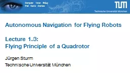
Lecture 31 3D Geometry Jürgen Sturm Technische Universität München Points in 3D 3D point Augmented vector Homogeneous coordinates Jürgen Sturm Autonomous Navigation for Flying Robots ID: 675097

sturm navigation autonomous flying navigation sturm flying autonomous rgen robots rotation szeliski camera http org called vector pitch vision

Share:

Link:

Embed:

Download Presentation from below link

Download Presentation The PPT/PDF document "Autonomous Navigation for Flying Robots" is the property of its rightful owner. Permission is granted to download and print the materials on this web site for personal, non-commercial use only, and to display it on your personal computer provided you do not modify the materials and that you retain all copyright notices contained in the materials. By downloading content from our website, you accept the terms of this agreement.


Presentation Transcript

Slide1

Autonomous Navigation for Flying RobotsLecture 3.1:3D Geometry

Jürgen

Sturm

Technische

Universität

MünchenSlide2

Points in 3D3D point

Augmented

vector

Homogeneous coordinates

Jürgen Sturm

Autonomous Navigation for Flying Robots

2Slide3

Geometric Primitives in 3D3D line through pointsInfinite

line:

Line

segment joining :Jürgen Sturm

Autonomous Navigation for Flying Robots

3Slide4

Geometric Primitives in 3D3D plane3D plane equationNormalized plane

with

unit normal

vector and distance Jürgen Sturm

Autonomous Navigation for Flying Robots

4Slide5

3D TransformationsTranslationEuclidean transform (translation + rotation), (also called the Special Euclidean group SE(3))

Scaled rotation, affine transform, projective transform…

Jürgen Sturm

Autonomous Navigation for Flying Robots

5Slide6

3D Euclidean TransformationsTranslation has 3 degrees of freedom

Rotation

has

3 degrees of freedomJürgen Sturm

Autonomous Navigation for Flying Robots

6Slide7

3D RotationsA rotation matrix is a 3x3 orthogonal matrix

Also

called the special orientation group SO(3

)Column vectors correspond to coordinate axes

Jürgen Sturm

Autonomous Navigation for Flying Robots

7Slide8

3D RotationsWhat operations do we typically do with rotation matrices?

Invert, concatenate

Estimate/optimize

How easy are these operations on matrices?Jürgen Sturm

Autonomous Navigation for Flying Robots

8Slide9

3D RotationsAdvantage: Can be easily concatenated and inverted (how?)Disadvantage:

Over-parameterized (

9 parameters instead of 3)

Jürgen Sturm

Autonomous Navigation for Flying Robots

9Slide10

Euler AnglesProduct of 3 consecutive rotations (e.g., around X-Y-Z axes)Roll-pitch-yaw convention is very common in aerial navigation (DIN 9300)

Jürgen Sturm

Autonomous Navigation for Flying Robots

10

http://en.wikipedia.org/wiki/File:Rollpitchyawplain.pngSlide11

Roll-Pitch-Yaw ConventionRoll , Pitch , YawConversion

to

3x3

rotation matrix:

Jürgen Sturm

Autonomous Navigation for Flying Robots

11Slide12

Roll-Pitch-Yaw ConventionRoll , Pitch , YawConversion

from

3x3

rotation matrix:

Jürgen Sturm

Autonomous Navigation for Flying Robots

12Slide13

Euler AnglesAdvantage:Minimal representation (3 parameters)Easy interpretation

Disadvantages:

Many “alternative” Euler representations exist (XYZ, ZXZ, ZYX, …)

Difficult to concatenateSingularities (gimbal lock)

Jürgen Sturm

Autonomous Navigation for Flying Robots

13Slide14

Gimbal LockWhen the axes align, one degree-of-freedom (DOF) is lost:

Jürgen Sturm

Autonomous Navigation for Flying Robots

14

http://commons.wikimedia.org/wiki/File:Rotating_gimbal-xyz.gifSlide15

Axis/AngleRepresent rotation byrotation axis androtation angle

4 parameters

3 parameters

length is rotation anglealso called the angular velocityminimal but not unique (why?)

Jürgen Sturm

Autonomous Navigation for Flying Robots

15Slide16

ConversionRodriguez’ formulaInverse

see:

An Invitation to 3D

Vision (Ma,

Soatto, Kosecka, Sastry

), Chapter 2

Jürgen Sturm

Autonomous Navigation for Flying Robots

16Slide17

Axis/AngleAlso called twist coordinatesAdvantages:Minimal representation

Simple derivations

Disadvantage:

Difficult to concatenateSlow conversionJürgen Sturm

Autonomous Navigation for Flying Robots

17Slide18

QuaternionsQuaternionReal and vector part

Unit

quaternions have

Opposite sign quaternions represent the same rotationOtherwise

unique

Jürgen SturmAutonomous Navigation for Flying Robots

18

Richard

Szeliski

, Computer Vision: Algorithms and

Applications

http

://szeliski.org/Book/Slide19

QuaternionsAdvantage: multiplication, inversion and rotations are very efficient

Concatenation

Inverse (=flip signs of real or imaginary part)

Rotate 3D vector using a quaternion:

Jürgen Sturm

Autonomous Navigation for Flying Robots

19Slide20

QuaternionsRotate 3D vector using a quaternion:Relation to

axis

/angle representation

Jürgen Sturm

Autonomous Navigation for Flying Robots

20Slide21

3D OrientationsNote: In general, it is very hard to “read” 3D orientations/rotations, no matter in what representation

Observation:

They are usually easy to visualize and can then be intuitively interpreted

Advice: Use 3D visualization tools for debugging (RVIZ, libqglviewer, …)

Jürgen Sturm

Autonomous Navigation for Flying Robots

21Slide22

3D to 2D Perspective ProjectionsJürgen Sturm

Autonomous Navigation for Flying Robots

22

Richard

Szeliski

, Computer Vision: Algorithms and Applications

http://szeliski.org/Book/Slide23

3D to 2D Perspective ProjectionsJürgen Sturm

Autonomous Navigation for Flying Robots

23

Richard

Szeliski

, Computer Vision: Algorithms and Applications

http://szeliski.org/Book/Slide24

3D to 2D Perspective ProjectionsJürgen Sturm

Autonomous Navigation for Flying Robots

24

Pin-hole

camera model

Note: is

homogeneous, needs to be normalizedSlide25

Camera IntrinsicsSo far, 2D point is given in meters on image planeBut: w

e

want 2D point be measured in pixels (as the sensor does

)Jürgen Sturm

Autonomous Navigation for Flying Robots

25

Richard

Szeliski

, Computer Vision: Algorithms and Applications

http://szeliski.org/Book/Slide26

Camera IntrinsicsNeed to apply some scaling/offset

Focal length

Camera center

SkewJürgen Sturm

Autonomous Navigation for Flying Robots

26Slide27

Camera ExtrinsicsAssume is given in world coordinatesTransform from world to camera (also called the camera

extrinsics

)

Projection of 3D world points to 2D pixel coordinates:

Jürgen Sturm

Autonomous Navigation for Flying Robots

27Slide28

Lessons Learned3D points, lines, planes

3D

transformations

Different representations for 3D orientationsChoice depends on applicationWhich representations do you remember?3D to 2D perspective projectionsYou

really have to know 2D/3D transformations by heart

(for more info, read Szeliski, Chapter 2, available online)

Jürgen Sturm

Autonomous Navigation for Flying Robots

28