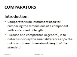
/
CMOS Comparators Offset Finite mismatch in the input pair lead to input-referred offset CMOS Comparators Offset Finite mismatch in the input pair lead to input-referred offset

CMOS Comparators Offset Finite mismatch in the input pair lead to input-referred offset - PowerPoint Presentation

faith
faith . @faith
Follow
67 views
Uploaded On 2023-10-25

CMOS Comparators Offset Finite mismatch in the input pair lead to input-referred offset - PPT Presentation

Offset can be cancelled by sampling it on a capacitor Chapter 10 Figure 2 Chapter 10 Figure 03 Offset cancellation Illustrated here with ideal switches Chapter 10 Figure 6 Practical offset cancellation ID: 1024498

input figure comparator offset figure input offset comparator dynamic chapter output referred vout vin observed clock regeneration comparators time

Share:

Link:

Embed:

Download Presentation from below link

Download Presentation The PPT/PDF document "CMOS Comparators Offset Finite mismatch ..." is the property of its rightful owner. Permission is granted to download and print the materials on this web site for personal, non-commercial use only, and to display it on your personal computer provided you do not modify the materials and that you retain all copyright notices contained in the materials. By downloading content from our website, you accept the terms of this agreement.


Presentation Transcript

1. CMOS Comparators

2. OffsetFinite mismatch in the input pair lead to input-referred offset in any differential amplifier or comparatorOffset can be cancelled by sampling it on a capacitorChapter 10 Figure 2Chapter 10 Figure 03

3. Offset cancellationIllustrated here with ideal switchesChapter 10 Figure 6

4. Practical offset cancellationMOS switches introduce charge injectionChapter 10 Figure 7

5. Fully-differential comparatorReduces impact of charge injection, common-mode noise, etc.Chapter 10 Figure 10

6. Chapter 10 Figure 4Use of opamps as a comparatorOpamps compensated for closed-loop stability have a slow dominant poleExample 10.2: time constant of the amplifier is t = 1/2p1kHz = 0.16msOpamps are slow when operated open-loopChapter 10 Figure 2t

7. Speed-up of opampCompensation may be disconnected during open-loop operationMay provide a speedup of 10-100 xChapter 10 Figure 5

8. Dynamic ComparatorsDynamic comparators use positive feedback to provide regenerative gain with much higher speedThey generally have less accuracy, more clock kickback, etc. than opamp-based comparatorsThey can be preceded by a preamplifier to improve their performanceChapter 10 Figure 15Chapter 10 Figure 14

9. Dynamic Comparator OperationChapter 10 Figure 15Chapter 10 Figure 18

10. Small-signal modelChapter 10 Figure 16

11. Need for RS LatchDynamic comparators generally have a “Reset” phase to minimize hysteresisMany applications will require them to be followed by a second latch stage that maintains the logic levels during the reset phaseExample: dynamic latch on the rightWhen Vltch is low, both Vout+ and Vout- are pulled up highChapter 10 Figure 19

12. Example RS LatchesO'Mahony, F. et al, "A 47 10 Gb/s 1.4 mW/Gb/s Parallel Interface in 45 nm CMOS," JSSC Dec. 2010SRQQ

13. Typical Dynamic Comparator ArchitecturePre-AmpRegenerative Positive-Feedback LatchRS LatchClockInputOutputReference(sometimes)

14. Key SpecificationsEnergy consumed per comparisonSystematic offsetHysteresisRandom offset Input sensitivityComparator input-referred noise

15. Energy per comparisonPower consumption @ fclk: P = VDDIDDFor a dynamic comparator, one expects: P = fclk CeffVDD2 + PstaticPstatic may include:Static power consumed in any preamplification stagesLeakageBias circuitryEnergy per conversion:Econv = Energy per sec / conv. per second = P / fclkAssuming dynamic power dominates, we expect this to be relatively constant:Econv = CeffVDD2Worst case will likely be at small input amplitudes (due to longer regeneration period) and toggling outputs (to maximize dynamic activity on all nodes)fclkDQDQVinVoutVDDIDD

16. Offset & HysteresisVin is a slow rampthe comparator is being continuously clockedWe expect the output to toggle on the first clock cycle after Vin crosses zeroIf this doesn’t happen, the input voltage required to toggle the output is the offsetIf the offset so observed is different when the input is increasing and decreasing, thenOffset is the average of the twoHysteresis is the difference Hysteresis may be caused by:Incomplete reset of the dynamic latchMemory in the RS latchfclkDQDQVinVoutVinVoutObserved with Vin increasingObserved with Vin decreasingVoffsetHysteresis

17. Random OffsetRepeating the experiment over many Monte Carlo runs will yield a Gaussian distribution of offset observationsThe mean offset observed is “systematic” offset; e.g. approximately -40mV on the rightCaused by asymmetries in the design, including layout parasiticsThe standard deviation of the observed comparator offsets is caused by random mismatchfclkDQDQVinVout

18. SensitivityWhen the input is very near the comparator’s trip point, it may take a long time before regeneration is completeIf the time to complete regeneration exceeds the clock period, the comparator is not able to resolve the inputExtreme case is when the output never resolves “Metastability”Chapter 10 Figure 18“Metastability”

19. Input-referred noiseWhen the input voltage is precisely set to the comparator trip point, noise will sometimes cause the comparator output to resolve high, sometimes lowRepeating the exercise many times can provide statistical data to which may be fit a Gaussian distributionThe standard deviation of the Gaussian is the comparator’s input-referred rms noiseOne must be careful to avoid the impact of input offset & hysteresisChapter 10 Figure 1fclkDQDQVin(small)Vout